Create and Manage Virtual Networks
Eventually, it all comes back to the network. Having servers running VMware ESX/ESXi with virtual machines stored on a highly redundant Fibre Channel SAN is great, but they are ultimately useless if the virtual machines cannot communicate across the network. What good is the ability to run 10 production systems on a single host at less cost if those production systems aren't available? Clearly, virtual networking within ESX/ESXi is a key area for every VMware administrator to understand fully.
Setting up a Virtual Network
Designing and building virtual networks with VMware ESX/ESXi and vCenter Server bears some similarities to designing and building physical networks, but there are enough significant differences that an overview of components and terminology is first warranted. So, I'll take a moment here to define the various components involved in a virtual network, and then I'll discuss some of the factors that affect the design of a virtual network:
•vNetwork Standard Switch (vSwitch) A software-based switch that resides in the VMkernel and provides traffic management for virtual machines. Users must manage vSwitches independently on each ESX/ESXi host.
•vNetwork Distributed Switch A software-based switch that resides in the VMkernel and provides traffic management for virtual machines, the Service Console, and the VMkernel. Distributed vSwitches are shared by and managed across entire clusters of ESX/ESXi hosts. You might see vNetwork Distributed Switch abbreviated as vDS;
•Port/port group A logical object on a vSwitch that provides specialized services for the Service Console, the VMkemel, or virtual machines. A virtual switch can contain a Service Console port, a VMkernel port, or a virtual machine port group. On a vNetwork Distributed Switch, these are called dvPort groups.
•Service Console port A specialized virtual switch port type that is configured with an IP address to allow access to the Service Console at the respective address. A Service Console port is also referred to as a vswif. Service Console ports are available only on VMware ESX because VMware ESXi does not have a Service Console.
•VMkernel port A specialized virtual switch port type that is configured with an IP address to allow VMotion, iSCSI storage access, network attached storage (NAS) or Network File System (NFS) access, or VMware Fault Tolerance (FT) logging. On VMware ESXi, a VMkernel port also provides management connectivity for managing the host. A VMkernel port is also referred to as a vmknic.
•Virtual machine port group A group of virtual switch ports that share a common configuration and allow virtual machines to access other virtual machines or the physical network.
• Virtual LAN A logical LAN configured on a virtual or physical switch that provides efficient traffic segmentation, broadcast control, security, and efficient bandwidth utilization by providing traffic only to the ports configured for that particular virtual LAN (VLAN).
• Trunk port (trunking) A port on a physical switch that listens for and knows how to pass traffic for multiple VLANs. It does this by maintaining the VLAN tags for traffic moving through the trunk port to the connected device(s). Trunk ports are typically used for switch-to-switch connections to allow VLANs to pass freely between switches. Virtual switches support VLANs, and using VLAN trunks allows the VLANs to pass freely into the virtual switches.
• Access port A port on a physical switch that passes traffic for only a single VLAN. Unlike a trunk port, which maintains the VLAN identification for traffic moving through the port, an access port strips away the VLAN information for traffic moving through the port.
• Network interface card team The aggregation of physical network interface cards (NICs) to form a single logical communication channel. Different types of NIC teams provide varying levels of traffic load balancing and fault tolerance.
• vmxnet adapter A virtualized network adapter operating inside a guest operating system. The vmxnet adapter is a high-performance, IGbps virtual network adapter that operates only if the VMware Tools have been installed. The vmxnet adapter is sometimes referred to as a para-virtualized driver. The vmxnet adapter is identified as Flexible in the virtual machine properties.
• vlance adapter A virtualized nehvork adapter operating inside a guest operating system. The vlance adapter is a lO/lOOMbps network adapter that is widely compatible with a range of operating systems and is the default adapter used until the VMware Tools installation is completed.
• e1000 adapter A virtualized network adapter that emulates the Intel elOOO network adapter. The Intel elOOO is a IGbps network adapter. The elOOO network adapter is most common in 64-bit virtual machines.
Now that you have a better understanding of the components involved and the terminology that you'll see in this chapter, I'll discuss how these components work together to form a virtual network in support of virtual machines and ESX/ESXi hosts.
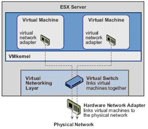
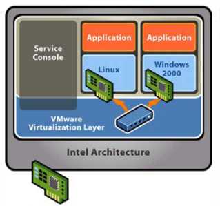
Virtual
Networking
Layer
Virtual Switch links virtual machines Luyelhar
Leading the way in IT testing an
Hardware Netwcrk Adapter Inks virtual machines the physical network
Physical Network
The answers to the following questions will, in large part, determine the design of your virtual networking:
• Do you have or need a dedicated network for management traffic, such as for the management of physical switches?
• Do you have or need a dedicated network for VMotion traffic?
• Do you have an IP storage network? Is this IP storage network a dedicated network? Are you running iSCSI or NAS/NFS?
• How many NICs are standard in your ESX/ESXi host design?
• Is there a need for extremely high levels of fault tolerance for VMs?
• Is the existing physical network comprised of VLANs?
• Do you want to extend the use of VLANs into the virtual switches?
As a precursor to setting up a virtual networking architecture, you need to identify and document the physical network components and the security needs of the network. It's also important to understand the architecture of the existing physical network, because that also greatly influences the design of the virtual network. If the physical network can't support the use of VLANs, for example, then the virtual network's design has to account for that limitation.
Successful virtual networking is a blend of virtual and physical network adapters and switches.
Because the virtual network implementation makes virtual machines accessible, it is essential that the virtual network is configured in a manner that supports reliable and efficient communication around the different network infrastructure components.
Working with vNetwork Standard Switches
The networking architecture of ESX/ESXi revolves around the creation and configuration of virtual switches (vSwitches). These virtual switches are either vNetwork Standard Switches or vNetwork Distributed Switches. In this section, I'll discuss vNetwork Standard Switches, hereafter called vSwitches; I'll discuss vNetwork Distributed Switches in the next section.
You create and manage vSwitches through the vSphere Client or through the VMware ESX Service Console (hereafter called the Service Console, because you know by now that ESXi does not have a Service Console) using the esxcfg-vswitch command, but they operate within the VMkernel. Virtual switches provide the connectivity to provide communication:
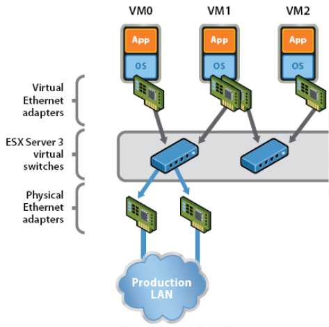
• between virtual machines within an ESX/ESXi host
• between virtual machines on different ESX/ESXi hosts
• between virtual machines and physical machines on the network
• for Service Console access (ESX only), and
• for VMkernel access to networks for VMotion, iSCSI, NFS, or fault tolerance logging (and management on ESXi)
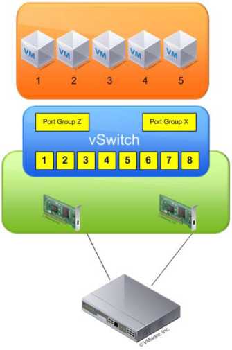
The vSwitches aren't depicted alone; they also require ports or port groups and uplinks. Without uplinks, a virtual switch can't communicate with the rest of the network; without ports or port groups, a vSwitch cannot provide connectivity for the Service Console, the VMkernel, or virtual machines. It is for this reason that most of our discussion about virtual switches centers on ports, port groups, and uplinks.
Creating and Configuring a virtual switch
First, though, let's take a closer look at vSwitches and how they are both similar to, yet different from, physical switches in the network.
By default every virtual switch is created with 64 ports. However, only 56 of the ports are available, and only 56 are displayed when looking at a vSwitch configuration through the vSphere Client. Reviewing a vSwitch configuration via the esxcfg-vswi tch command shows the entire 64 ports.
The eight-port difference is attributed to the fact that the VMkernel reserves eight ports for its own use. After a virtual switch is created, you can adjust the number of ports to 8, 24, 56, 120, 248, 504, or 1016. These are the values that are reflected in the vSphere Client. But, as noted, there are eight ports reserved, and therefore the command line will show 32, 64, 128, 256, 512, and 1,024 ports for virtual switches.
Changing the number of ports in a virtual switch requires a reboot of the ESX/ESXi host on which the vSwitch was altered.
Comparing Virtual Switches and Physical Switches
Virtual switches in ESX/ESXi are constructed by and operate in the VMkernel. Virtual switches, or vSwitches, are not managed switches and do not provide all the advanced features that many new physical switches provide. You cannot, for example, telnet into a vSwitch to modify settings. There is no command-line interface (CLI) for a vSwitch. Even so, a vSwitch operates like a physical switch in some ways. Like its physical counterpart, a vSwitch functions at Layer 2, maintains MAC address tables, forwards frames to other switch ports based on the MAC address, supports VLAN configurations, is capable of trunking using iEEE 802.1q VLAN tags, and is capable of establishing port channels. Similar to physical switches, vSwitches are configured with a specific number of ports.
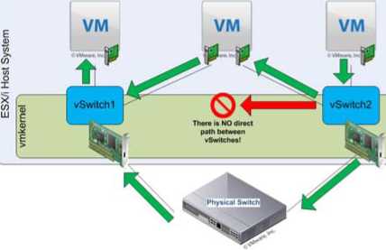
Despite these similarities, vSwitches do have some differences from physical switches. A vSwitch does not support the use of dynamic negotiation protocols for establishing 802.1q trunks or port channels, such as Dynamic Trunking Protocol (DTP) or Port Aggregation Protocol (PAgP). A vSwitch cannot be connected to another vSwitch, thereby eliminating a potential loop configuration. Because there is no possibility of looping, the vSwitches do not run Spanning Tree Protocol (STP).
Looping can be a common network problem, so this is a real benefit of vSwitches.
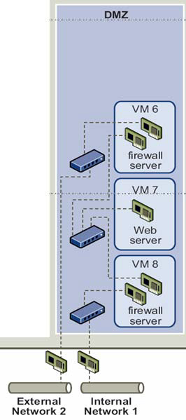
It is possible to link vSwitches together using a virtual machine with Layer 2 bridging software and multiple virtual NICs, but this is not an accidental configuration and would require some effort to
External Network 2
Internal Network 1
establish. Some other differences of vSwitches from physical switches include the following:
• A vSwitch authoritatively knows the MAC addresses of the virtual machines connected to that vSwitch, so there is no need to learn MAC addresses from the network.
• Traffic received by a vSwitch on one uplink is never forwarded out another uplink. This is yet another reason why vSwitches do not run STP.
• A vSwitch does not need to perform Internet Group Management Protocol (IGMP) snooping because it knows the multicast interests of the virtual machines attached to that vSwitch.
As you can see front this list of differences, you simply can't use virtual switches in the same way you can use physical switches. You can't use a virtual switch as a transit path between two physical switches, for example, because traffic received on one uplink won't be forwarded out another uplink. With this basic understanding of how vSwitches work, let's now take a closer look at ports and port groups.
Understanding Ports and Port Groups
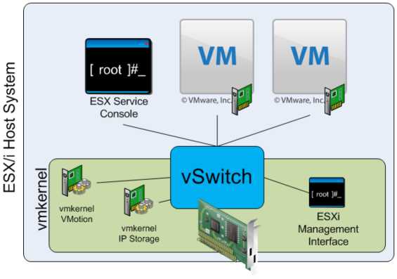
As described previously in this chapter, a vSwitch allows several different types of communication, including communication to and from the Service Console, to and from the VMkernel, and between virtual machines. To help distinguish between these different types of communication, ESX/ESXi uses ports and port groups. A vSwitch without any ports or port groups is like a physical switch that has no physical ports; there is no way to connect anything to the switch, and it is, therefore, useless.
Port groups differentiate between the types of traffic passing through a vSwitch, and they also operate as a boundary for communication and/or security policy configuration. Figure 3.3 show the three different types of ports and port groups that you can configure on a vSwitch:
• Service Console port
• VMkernel port
• Virtual Machine port group
Because a vSwitch cannot be used in any way without at least one port or port group, you'll see that the vSphere Client combines the creation of new vSwitches with the creation of new ports or port groups.
Ports and port groups are only part of the overall solution. The uplinks are the other part of the solution that you need to consider because they provide external network connectivity to the vSwitches.
Understanding Uplinks
Although a vSwitch provides for communication between virtual machines connected to the vSwitch, it cannot communicate with the physical network without uplinks. Just as a physical switch must be connected to other switches in order to provide communication across the network, vSwitches must be connected to the ESX/ESXi host's physical NICs as uplinks in order to communicate with the rest of the network.
Unlike ports and port groups, uplinks aren't necessarily required in order for a vSwitch to function. Physical systems connected to an isolated physical switch that has no uplinks to other physical switches in the network can still communicate with each other-just not with any other systems that are not connected to the same isolated switch. Similarly, virtual machines connected to a vSwitch without any uplinks can communicate with each other but cannot communicate with virtual machines on other vSwitches or physical systems.
This sort of configuration is known as an internal-only vSwitch. It can be useful to allow virtual machines to communicate with each other, but not with any other systems. Virtual machines that communicate through an internal-only vSwitch do not pass any traffic through a physical adapter on the ESX/ESXi host. Communication between virtual machines connected to an internal-only vSwitch takes place entirely in software and happens at whatever speed the VMkernel can perform the task.
For virtual machines to communicate with resources beyond the virtual machines hosted on the local ESX/ESXi host, a vSwitch must be configured to use at least one physical network adapter, or uplink. A vSwitch can be bound to a single network adapter or bound to two or more network adapters.
A vSwitch bound to at least one physical network adapter allows virtual machines to establish communication with physical servers on the network or with virtual machines on other ESX/ESXi hosts. That's assuming, of course, that the virtual machines on the other ESX/ESXi hosts are connected to a vSwitch that is bound to at least one physical network adapter. Just like a physical network, a virtual network requires connectivity from end to end. Figure 5.6 shows the communication path for virtual machines connected to a vSwitch bound to a physical network adapter. In the diagram, when VMl on ESX1 needs to communicate with VM2 on ESX2, the traffic from the virtual machine passes through vSwitch0 (via a virtual machine port group) to the physical network adapter to which the vSwitch is bound. From the physical network adapter, the traffic will reach the physical switch (PhySw1). The physical switch (PhySw1) passes the traffic to the second physical switch (PhySw2), which will pass the traffic through the physical network adapter associated with the vSwitch on ESX2. In the last stage of the communication, the vSwitch will pass the traffic to the destination virtual machine VM2.
The vSwitch associated with a physical network adapter provides virtual machines with the amount of bandwidth the physical adapter is configured to support. All the virtual machines will share this bandwidth when communicating with physical machines or virtual machines on other ESX/ESXi hosts. In this way, a vSwitch is once again similar to a physical switch. For example, a vSwitch bound to a network adapter with a 1 Gbps maximum speed will provide up to 2 Gbps worth of bandwidth for the virtual machines connected to it; similarly, a physical switch with a lGbps uplink to another physical switch provides up to lGbps of bandwidth between the two switches for systems attached to the physical switches.
A vSwitch can also be bound to multiple physical network adapters. In this configuration, the vSwitch is sometimes referred to as a NIC team, but in this guide I'll use the term NIC team or NIC teaming to refer specifically to the grouping of network connections together, not to refer to a vSwitch with multiple uplinks.
Figure 5.7 show a vSwitch bound to multiple physical network adapters. A vSwitch can have a maximum of 32 uplinks. In other words, a single vSwitch can use up to 32 physical network adapters to send and receive traffic from the physical switches. Binding multiple physical NICs to a vSwitch offers the advantage of redundancy and load distribution.
So, you've examined vSwitches, ports and port groups, and uplinks, and you should have a basic understanding of how these pieces begin to fit together to build a virtual network. The next step is to delve deeper into the configuration of the various types of ports and port groups, because they are so essential to virtual networking.
Configuring Service Console Networking
Recall that the Service Console port is one of three types of ports or port groups you can create on a vSwitch. As shown in Figure 5.9, the Service Console port acts as a passage into the management and monitoring capabilities of the console operating system.
Although the vSphere Client masks most of this complexity, there are actually two different parts to Service Console networking. The first part is the Service Console port on the vSwitch; the second part is the vswif interface.
The Service Console port on the vSwitch defines connectivity information such as the VLAN ID, policy information such as the NIC failover order, and which uplinks the Service Console port may use to communicate with external entities. To display or modify this information, use the esxcfg-vswitch command from the Service Console or use the vSphere Client.
The vswif interface, on the other hand, is the logical network interface that is created within the Linux-based Service Console. The vswif is where the IP address is assigned. Commands like ipconfig or esxcfg-vswif will display information about the vswif interface.
Technically speaking, the vswif is not the Service Console port, or vice versa. For a vswif interface to exist, there will always be a Service Console port, but in order for a Service Console port to exist, there does not need to be a vswif.
Configuring VMkernel Networking
VMkernel ports provide network access for the VMkernel's TCPIP stack, which is separate and independent from the Service Console TCPIP stack. VMkernel ports are used for VMotion, iSCSI, NAS/NFS access, and VMware FT. With ESXi, VMkernel ports are also used for management. In later chapters I detail the iSCSI and NAS/NFS configurations, as well as the details of the VMotion process and how VMware FT works.
These discussions provide insight into the traffic flow between VMkernel and storage devices (iSCSI/NFS) or other ESX/ESXi hosts (for VMotion or VMware FT). At this point, you should be concerned only with configuring VMkernel networking.
Like a Service Console port, a VMkernel port actually comprises two different components: a port on a vSwitch and a VMkernel network interface, also known as a vmknic. And like a Service Console port, creating a VMkernel port using the vSphere Client combines the task of creating the port group and the VMkernel NIC. Unlike a Service Console port, there is no need for administrative access to the IP address assigned to a VMkernel port.
Configuring Management Networking (ESXi Only)
Because ESXi lacks a Linux-based Service Console like ESX, the idea of how management networking works with ESXi is quite different. Instead of using Service Console ports, ESXi uses VMkernel ports. To help distinguish the various types of
VMkernel ports, ESXi offers an option to enable management traffic on a VMkernel port. Figure 5.18 illustrates this. To create additional management network interfaces, you would use the procedure described previously for creating VMkernel ports using the vSphere Client, simply enabling the Use This Port Group For Management Traffic option while creating the port.
In the event that the ESXi host is unreachable-and therefore cannot be configured using the vSphere Client-you need to use the ESXi interface to configure the management network. Perform the following steps to configure the ESXi management network using the ESXi console:
1. At the server's physical console or using a remote console utility such as the HP iLO, press F2 to enter the System Customization menu. If prompted to log in, enter the appropriate credentials.
2. Use the arrow keys to highlight the Configure Management Network option
3. From the Configure Management Network menu, select the appropriate option for configuring ESXi management networking. You cannot create additional management network interfaces from here; you can only modify the existing management network interface.
4. When finished, follow the screen prompts to exit the management networking configuration. If prompted to restart the management networking, select Yes; otherwise, restart the management networking from the System Customization menu
In the Configure Management Network Menu, you'll also see options for testing the management network, which lets you be sure that the management network is configured correctly. This is invaluable if you are unsure of the VLAN ID or network adapters that you should use. Only one type of port or port group remains, and that is a virtual machine port group.
Configuring Virtual Machine Networking
The last connection type (or port group) to discuss is the virtual machine port group. The virtual machine port group is quite different from a Service Console port or a VMkernel port. Both of the other ports have a one-to-one relationship with an interface-each Service Console interface, or vswif, requires a matching Service Console port on a vSwitch, and each VMkernel NIC, or vmknic, requires a matching VMkernel on a vSwitch. In addition, these interfaces require IP addresses that are used for management or VMkernel network access.
A virtual machine port group, on the other hand, does not have a one-to-one relationship, and it does not require an IP address. For a moment, forget about vSwitches, and consider standard physical switches. When you install an unmanaged physical switch into your
network environment, that physical switch does not require an IP address. Adding unmanaged physical switches does not require IP addresses; you simply install the switches and plug in the appropriate uplinks that will connect them to the rest of the network.
Ports and port groups on a virtual switch
AvSwitch can consist of multiple connection types, or each connection type can be created in its own vSwitch
A vSwitch created with a Virtual Machine port group is really no different. A vSwitch with a Virtual Machine port group acts just like an additional unmanaged physical switch. You need only plug in the appropriate uplinks-physical network adapters, in this case-that will connect that vSwitch to the rest of
the network. As with an unmanaged physical switch, an IP address does not need to be configured for a Virtual Machine port group to combine the ports of a vSwitch with those of a physical switch.
Of the three different connection types-Service Console port, VMkernel port, and virtual machine port group-vSphere administrators will spend most of their time creating, modifying, managing, and removing virtual machine port groups.
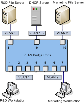
Configuring VLANs
Several times so far we've referenced the use of the VLAN ID when configuring a Service Console port, a VMkernel port, or a virtual machine port group. As defined previously in this chapter, a virtual LAN (VLAN) is a logical LAN that provides efficient segmentation, security, and broadcast control while allowing traffic to share the same physical LAN segments or same physical switches. Figure 5.23 shows a typical VLAN configuration across physical switches.
Using VLAN ID 4095
Normally the VLAN lD will range from 1 to 4094. In the ESX/ESXi environment, however, a VLAN lD of 4095 is also valid. Using this VLAN lD with ESX/ESXi causes the VLAN tagging information to be passed through the vSwitch all the way up to the guest operating system. This is called virtual guest tagging (VGT) and is useful only for guest operating systems that support and understand VLAN tags.
VLANs utilize the IEEE 802.1Q standard for tagging, or marking, traffic as belonging to a particular VLAN. The VLAN tag, also known as the VLAN ID, is a numeric value between 1 and 4094, and it uniquely identifies that VLAN across the network. Physical switches such as the ones depicted in Figure 5.23 must be configured with ports to trunk the VLANs across the switches. These ports are known as trunk (or trunking) ports. Ports not configured to trunk VLANs are known as access ports and can carry traffic only for a single VLAN at a time.
VLANs are an important part of ESX/ESXi networking because of the impact they have on the number of vSwitches and uplinks that are required. Consider this:
The Service Console (or the Management Network in ESXi) needs access to the network segment carrying management traffic.
VMkernel ports, depending upon their purpose, may need access to an isolated VMotion segment or the network segment carrying iSCSI and NAS/NFS traffic.
Virtual machine port groups need access to whatever network segments are applicable for the virtual machines running on the ESX/ESXi hosts.
Without VLANs, this configuration would require three or more separate vSwitches, each bound to a different physical adapter, and each physical adapter would need to be physically connected to the correct network segment, as illustrated in Figure 5.24.
Add in an IP-based storage network and a few more virtual machine networks that need to be supported, and the number of required vSwitches and uplinks quickly grows. And this doesn't even take uplink redundancy, for example NIC teaming, into account!
VLANs are the answer to this dilemma. Figure 5.25 shows the same network as in Figure 5.24, but with VLANs this time.
While the reduction from Figure 5.24 to Figure 5.25 is only a single vSwitch and a single uplink, you can easily add more virtual machine networks to the configuration in Figure 5.25 by simply adding another port group with another VLAN ID. Blade servers provide an excellent example of when VLANs offer tremendous benefit. Because of the small form factor of the blade casing, blade servers have historically offered limited expansion slots for physical network adapters. VLANs allow these blade servers to support more networks than they would be able to otherwise.
No vLAN Needed
Virtual switches in the VMkernel do not need VLANs if an ESX/ESXi host has enough physical network adapters to connect to each of the different network segments. However, VLANs provide added flexibility in adapting to future network changes, so the use of VLANs where possible is recommended.
As shown in Figure 5.25, VLANs are handled by configuring different port groups within a vSwitch. The relationship between VLANs is not a one-to-one relationship; a port group can be associated with only one VLAN at a time, but multiple port groups can be associated with a single VLAN.
To make VLANs work properly with a port group, the uplinks for that vSwitch must be connected to a physical switch port configured as a trunk port. A trunk port understands how to pass traffic from multiple VLANs simultaneously while also preserving the VLAN IDs on the traffic.
When the physical switch ports are correctly configured as trunk ports, the physical switch passes the VLAN tags up to the ESX/ESXi server, where the vSwitch tries to direct the traffic to a port group with that VLAN ID configured. If there is no port group configured with that VLAN ID, the traffic is discarded.
Configuring NIC Teaming
We know that in order for a vSwitch and its associated ports or port groups to communicate with other ESX/ESXi hosts or with physical systems, the vSwitch must have at least one uplink.
An uplink is a physical network adapter that is bound to the vSwitch and connected to a physical network switch. With the uplink connected to the physical network, there is connectivity for the Service Console,
VMkernel, or virtual machines connected to that vSwitch. But what happens when that physical network adapter fails, when the cable connecting that uplink to the physical network fails, or the upstream physical switch to which that uplink is connected fails? With a single uplink, network connectivity to the entire vSwitch and all of its ports or port groups is lost.
This is where NIC teaming comes in. NIC teaming involves connecting multiple physical network adapters to single vSwitch. NIC teaming provides redundancy and load balancing of network communications to Service Console, VMkernel, and virtual machines.
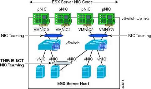
Figure 5.28 illustrates NIC teaming conceptually. Both of the vSwitches have two uplinks, and each of the uplinks connects to a different physical switch. Note that NIC teaming supports all the different connection types, so it can be used with Service Console networking, VMkernel networking, and networking for virtual machines.
As mentioned in the previous section, the ESX/ESXi host can have a maximum of 32 uplinks; these uplinks can be spread across multiple vSwitches or all tossed into a NIC team on one vSwitch. Remember that you can connect a physical NIC to only one vSwitch at a time.
Building a functional NIC team requires that all uplinks be connected to physical switches in the same broadcast domain. If VLANs are used, then all the switches should be configured for VLAN trunking, and the appropriate subset of VLANs must be allowed across the VLAN trunk. In a Cisco switch, this is typically controlled with the switchport trunk allowed v1an statement.
In Figure 5.30, the NIC team for vSwitch0 will work, because both of the physical switches share VLAN l00 and are therefore in the same broadcast domain. The NIC team for vSwitchl, however, will not work because the physical network adapters do not share a common broadcast domain.
After an NIC team is established for a vSwitch, ESX/ESXi can then perform load balancing for that vSwitch. The load-balancing feature of Nrc teaming does not function like the load-balancing feature of advanced routing protocols. Load balancing across a NIC team is not a product of identifying the amount of traffic transmitted through a network adapter and shifting traffic to equalize data flow through all available adapters. The load-balancing algorithm for NIC teams in a vSwitch is a balance of the number of connections-not the amount of traffic. NIC teams on a vSwitch can be configured with one of the following three load-balancing policies:
• vSwitch port-based load balancing (default)
• Source MAC-based load balancing
• IP hash-based load balancing
Virtual switch port load balancing
The vSwitch port-based load-balancing policy that is used by default uses an algorithm that ties each virtual switch port to a specific uplink associated with the vSwitch. The algorithm attempts to maintain an equal number of port-to-uplink assignments across all uplinks to achieve load balancing. As shown in Figure 5.32, this policy setting ensures that traffic from a specific virtual network adapter connected to a virtual switch port will consistently use the same physical network adapter. In the event that one of the uplinks fails, the traffic from the failed uplink will failover to another physical network adapter.
You can see how this policy does not provide load balancing but rather redundancy. Because the port to which a virtual machine is connected does not change, each virtual machine is tied to a physical network adapter until failover occurs regardless of the amount of network traffic that is generated. Looking at Figure 5.32, imagine that the Linux virtual machine and the Windows virtual machine on the far left are the two most network-intensive virtual machines. In this case, the vSwitch port-based policy has assigned both of the ports used by these virtual machines to the same physical network adapter. This could create a situation in which one physical network adapter is much more heavily utilized than some of the other network adapters in the NIC team.
The physical switch passing the traffic learns the port association and therefore sends replies back through the same physical network adapter from which the request initiated. The vSwitch port-based policy is best used when the number of virtual network adapters is greater than the number of physical network adapters. In the case where there are fewer virtual network adapters than physical adapters, some physical adapters will not be used. For example, if five virtual machines are connected to a vSwitch with six uplinks, only five used vSwitch ports will be assigned to exactly five uplinks, leaving one uplink with no traffic to process.
Source MAC Load Balancing
The second load-balancing policy available for a NIC team is the source MAC-based policy, shown in Figure 5.33. This policy is susceptible to the same pitfalls as the vSwitch port-based policy simply because the static nature of the source MAC address is the same as the static nature of a vSwitch port assignment. Like the vSwitch port-based policy, the source MAC-based policy is best used when the number of virtual network adapters exceeds the number of physical network adapters. In addition, virtual machines are still not capable of using multiple physical adapters unless configured with multiple virtual network adapters. Multiple virtual network adapters inside the guest operating system of a virtual machine will provide multiple source MAC addresses and therefore offer an opportunity to use multiple physical network adapters.
Virtual switch to physical switch
To eliminate a single point of failure, you can connect the physical network adapters in NIC teams set to use the vSwitch port-based or source MAC-based load-balancing policies to different physical switches; however, the physical switches must belong to the same Layer 2 broadcast domain. Link aggregation using 802.3ad teaming is not supported with either of these load-balancing policies.
IP Hash Load Balancing
The third load-balancing policy available for NIC teams is the IP hash-based policy, also called the out-IP policy. This policy, shown in Figure 5.34, addresses the limitation of the other two policies that prevents a virtual machine from accessing two physical network adapters without having two virtual network adapters. The IP hash-based policy uses the source and destination IP addresses to determine the physical network adapter for communication. This algorithm then allows a single virtual machine to communicate over different physical network adapters when communicating with different destinations.
Unless the physical hardware supports it, a vSwitch with the NIC teaming load-balancing policy set to use the IP-based hash must have all physical network adapters connected to the same physical switch. Some newer switches support link aggregation across physical switches, but otherwise all the physical network adapters will need to connect to the same switch. In addition, the switch must be configured for link aggregation. ESX/ESXi supports standard 802.3ad teaming in static (manual) mode but does not support the Link Aggregation Control Protocol (LACP) or Port Aggregation Protocol (PAgP) commonly found on switch devices. Link aggregation will increase throughput by combining the bandwidth of multiple physical network adapters for use by a single virtual network adapter of a virtual machine.
Let's take a deeper look at the failover and failback of uplinks in a NIC team. There are two parts to consider: failover detection and failover policy.
Failover detection with NIC teaming can be configured to use either a link status method or a beacon probing method. The link status failover detection method works just as the name suggests. Failure of an uplink is identified by the link status provided by the
physical network adapter. In this case, failure is identified for events like removed cables or power failures on a physical switch. The downside to the link status failover detection setting is its inability to identify mis-configurations or pulled cables that connect the switch to other networking devices (for example, a cable connecting one switch to an upstream switch.)
The beacon probing failover detection setting, which includes link status as well, sends Ethernet broadcast frames across all physical network adapters in the NIC team. These broadcast frames allow the vSwitch to detect upstream network connection failures and will force failover when Spanning Tree Protocol blocks ports, when ports are configured with the wrong VLAN, or when a switch-to-switch connection has failed. When a beacon is not returned on a physical network adapter, the vSwitch triggers the failover notice and reroutes the traffic from the failed network adapter through another available network adapter based on the failover policy.
Consider a vSwitch with a NIC team consisting of three physical network adapters, where each adapter is connected to a different physical switch and each physical switch is connected to a single physical switch, which is then connected to an upstream switch, as shown in Figure 5.37. When the NIC team is set to the beacon probing failover detection method, a beacon will be sent out over all three uplinks.
After a failure is detected, either via link status or beacon probing, a failover will occur. Traffic from any virtual machines or any Service Console or VMkernel ports is rerouted to another member of the NIC team. Exactly which member that might be, though, depends primarily upon the configured failover order.
The Failback option controls how ESX/ESXi will handle a failed network adapter when it recovers from failure. The default setting, Yes, indicates the adapter will be returned to active duty immediately upon recovery, and it will replace any standby adapter that may have taken its place during the failure. Setting Failback to No means that the recovered adapter remains inactive until another adapter fails, triggering the replacement of newly failed adapter.
When a failover event occurs on a vSwitch with a NIC team, the vSwitch is obviously aware of the event. The physical switch that the vSwitch is connected to, however, will not know immediately. A vSwitch includes a Notify Switches configuration setting, which, when set to Yes, will allow the physical switch to immediately learn of any of the following changes:
• A virtual machine is powered on (or any other time a client registers itself with the vSwitch)
• A VMotion occurs
• A MAC address is changed
• A NIC team failover or failback has occurred
Traffic Shaping
By default, all virtual network adapters connected to a vSwitch have access to the full amount of bandwidth on the physical network adapter with which the vSwitch is associated. In other words, if a vSwitch is assigned a IGbps network adapter, then each virtual machine configured to use the vSwitch has access to IGbps of bandwidth. Naturally, if contention becomes a bottleneck hindering virtual machine performance, NIC teaming will help. However, as a complement to NIC teaming, it is also possible to enable and to configure traffic shaping. Traffic shaping involves the establishment of hard-coded limits for peak bandwidth, average bandwidth, and burst size to reduce a virtual machine's outbound bandwidth capability.
The peak bandwidth value and the average bandwidth value are specified in kilobits per second, and the burst size is configured in units of kilobytes. The value entered for the average bandwidth dictates the data transfer per second across the virtual vSwitch. The peak bandwidth value identifies the maximum amount of bandwidth a vSwitch can pass without dropping packets. Finally, the burst size defines the maximum amount of data included in a burst. The burst size is a calculation of bandwidth multiplied by time. During periods of high utilization, if a burst exceeds the configured value, packets are dropped in favor of other traffic; however, if the queue for network traffic processing is not full, the packets are retained for transmission at a later time.
Bringing It All Together
By now you've seen how all the various components of ESX/ESXi virtual networking interact with each other-vSwitches, ports and port groups, uplinks and NIC teams, and VLANs. But how do you assemble all these pieces together into a usable whole?
The number and the configuration of the vSwitches and port groups are dependent on several factors, including the number of network adapters in the ESX/ESXi host, the number of IP subnets, the existence of VLANs, and the number of physical networks. With respect to the configuration of the vSwitches and virtual machine port groups, there is no single correct configuration that will satisfy every scenario. It is true, however, to say that the greater the number of physical network adapters in an ESX/ESXi host, the more flexibility you will have in your virtual networking architecture.
If the vSwitches created in the VMkernel are not going to be configured with multiple port groups or VLANs, you will be required to create a separate vSwitch for every IP subnet or physical network to which you need to connect. To really understand this concept, let's look at two more examples.
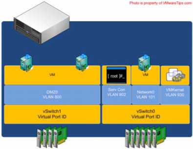
Figure 5.44 shows a scenario in which there are five IP subnets that your virtual infrastructure components need to reach. The virtual machines in the production environment must reach the production LAN, the virtual machines in the test environment must reach the test LAN, the VMkernel needs to access the IP storage and VMotion LANs, and finally the Service Console must be on the management LAN. In this scenario, without the use of VLANs and port groups, the ESX/ESXi host must have five different vSwitches and five different physical network adapters. (Of course, this doesn't account for redundancy or NIC teaming for the vSwitches.)
Figure 5.45 shows the same configuration, but this time using VLANs for the Management, VMotion, Production, and Test/Dev networks. The IP storage network is still a physically separate network.
The configuration in Figure 5.45 still uses five network adapters, but this time you're able to provide NIC teaming for all the networks except for the IP storage network. If the IP storage network had been configured as a VLAN, the number of vSwitches and uplinks could have been even further reduced. Figure 5.46 shows a possible configuration that would support this sort of scenario.
This time, you're able to provide NIC teaming to all the traffic types involved-Service Console/Management traffic, VMotion, IP storage, and the virtual machine traffic-using only a single vSwitch with multiple uplinks.
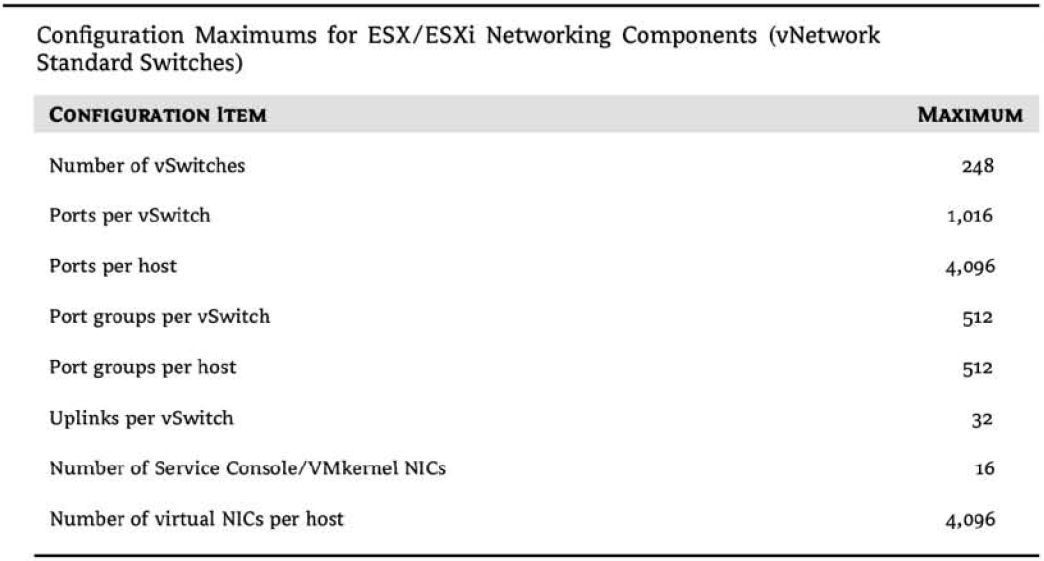
Clearly, there is a tremendous amount of flexibility in how vSwitches, uplinks, and port groups are assembled to create a virtual network capable of supporting your infrastructure. Even given all this flexibility, though, there are limits. Table 3.2 lists some of the limits of ESX/ESXi networking.
Virtual switch configurations. Don't go too big!
Although you can create a vSwitch with a maximum of 1,016 ports (really 1,024), it is not recommended if you anticipate growth. Because ESX/ESXi hosts cannot have more than 4,096 ports, if you create vSwitches with 1,016 ports, then you are limited to only 4 vSwitches (1,024 x 4). With room for only four vSwitches, you may not be able to connect to all the networks that you need. I recommend creating virtual switches with just enough ports to cover existing needs and projected growth. In the event you do run out of ports on an ESX/ESXi host and need to create a new vSwitch, you can reduce the number of ports on an existing vSwitch. That change requires a reboot to take effect, but VMotion allows you to move the VMs to a different host to prevent VM downtime.
With all the flexibility provided by the different virtual networking components, you can be assured that whatever the physical network configuration might hold in store, there are several ways to integrate the virtual networking. What you configure today may change as the infrastructure changes or as the hardware changes. ESX/ESXi provides enough tools and options to ensure a successful communication scheme between the virtual and physical networks.