9 Install, configure, and differentiate among common network devices
A network uses multiple devices like switches, routers, bridges, firewalls, modems, AP's etc. It is the job of a Network Administrator to configure and monitor these devices. Dealing with these devices one by one:
Hubs: These are simple network devices. These are not very costly and yet provide everything that is necessary to construct a small network. Hubs with higher number of ports are easily available for networks with higher capacity. The figure given below illustrates a workgroup hub.
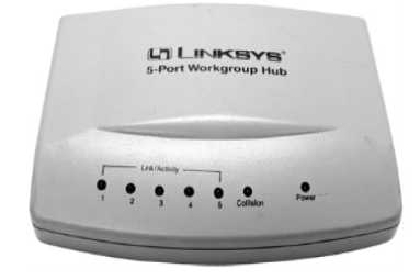
Figure 25: A Workgroup Hub
A twisted pair cable is used to connect a computer to a hub. An uplink port allows a hub to be connected to another hub for building bigger networks. Hubs are primarily of two kinds:
- Active Hubs: Data signal is regenerated by these hubs before forwarding it to the other ports on the device. Active Hubs require a power supply. For smaller workgroup hubs, external power adapter is used and in the case of larger units the power supply is in built.
- Passive Hubs: Passive Hubs can only be seen on older networks. These do not need any power supply and do not regenerate data signal.
The figure illustrated below shows how a connection between a Hub and a Workstation is made.
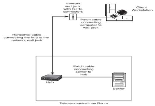
Figure 26: Connection between a Hub and a Workstation
The basic functions of a hub are:
- Regeneration of the signal;
- To take data from a connected device and forwarding it to other ports. The figure given below illustrates how a hub functions.
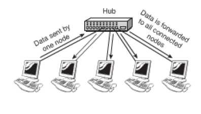
Figure 27: Working of a Hub
Hubs are being replaced with switches as the need for bandwidth is increasing day by day.
Network Switches: A switch and a hub look quite the same, but their efficiencies and operations are way apart. Switches are more efficient than hubs. The figure below illustrates a 32-port Ethernet switch.
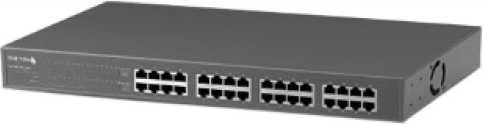
Figure 28: An Ethernet Switch
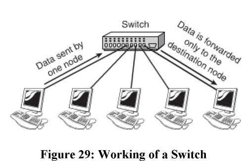
Switches too connect to computers using a length of twisted-pair cable. Larger networks are set up using multiple switches are often interconnected to create larger networks. A switch unlike a hub does not forward data to all the ports that are connected to it but rather to only those ports on which the system is connected. It uses the MAC (Media Access Control) addresses of the devices connected to it to determine the destination. In every NIC is stamped a unique address which serves as the MAC address. By selective forwarding of data, a switch is able to control the amount of traffic on a particular network link. The figure given below illustrates how a switch works.
Hubs work in two modes:
- Half Duplex: On a standard network, half duplex is the term used to refer to the communication between the system and the switch. In this mode data is either received or sent.
- Full Duplex: In the full duplex mode, the maximum throughput is fifty percent more than the half duplex connection. This further enhances the performance of the network. Switches isolate each port and create separate segments for each port on the switch; as a result there are only two devices on each segment. In this mode there are no collisions occur, this also means that there is no need to have a collision detection system. The conventional approach of carrier-sense multiple-access with collision detection (CSMA/CD) media access method is dropped. A full duplex connection requires three components to be formed. These components are a switch, a cable and a NIC that is capable of supporting a full duplex communication.
Switching Methods: Switches deal with data in three ways, or it can also be said that switches can be configured in three ways:
- Cut Through: In this configuration, the packet is forwarded the moment it is received. The packet is not checked for errors and it is made to move quickly. The short coming of this method is that it spreads errors. It is much faster than any other method and seems to be the obvious choice.
- Store-and-forward: In this form of configuration, the entire packet is received, a basic error check is done and then the same is forwarded. This method takes a little longer and the size of the packet grows heavy, but it is more reliable.
- Fragment-free: This form works by reading only a part of the packet that enables identification of fragments of a transmission.
Working with Hubs and Switches: Even though switches have their own advantages, in the older networks hubs can still be commonly seen. It is important to understanding the working of both the devices especially for the purposes of troubleshooting. To explain with the help on example, a hub may need to be replaced with a switch if the network is congested. Hubs as well as Switches have ports of two types:
- MDI (Medium Dependent Interface) - MDI-X (Medium Dependent Interface Crossover)
The difference in the ports is that of the wiring. In the second type the wiring is crossed, for the reason that the transmission wire from the connected device must be wired to the receiving line on the other end. A simple straight-through cable can also be used to connect systems to the switch or hub.
The hubs and switches that are used today allow connecting two hubs and switches for creating larger networks. On most modern hubs and switches, a special port called the uplink port allows you to connect two hubs and switches. Because the aim of this type of network connection is to make each hub or switch think that it is part of a larger network, the connection for the port is not crossed; a straight-through network cable connects the two hubs or switches. When you connect ports, remember that MDI-X is crossed MDI. If there is one device with MDI port and one device with MDI-X port, a straight-through cable is required. If both are MDI ports, a crossover cable is needed. Today, however, newer switches/routers have autosense ports, which means that you can use any type of cable (crossover or straight), and it will detect and cross lines if necessary. The figure given below illustrates an uplink Port on an Ethernet Switch.
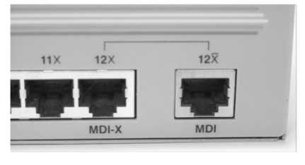
Figure 30: An uplink Port on an Ethernet Switch.
The prescribed standards state that as many as 1024 nodes are possible on a network, though actually the maximum is much lower. The numbers of nodes that can be effectively accommodated are much lower. Usage of switches changes the picture all together. The amount of traffic and the type of traffic are also two important influencing factors. Hybrid Switches are those switches that can accommodate different media types, such as fiber-optic cable and UTP. Some high end devices have empty sockets allowing plugging of connectivity modules as per the need. This helps to create fast networks.
Hub and Switch Indicator Lights: LED's are used by both hubs as well as switches for indicating the connection conditions. These lights indicate activity, speed, errors and collisions and even the nature of the connection that is whether it is half duplex or full duplex. The hubs and switches are available as rack mountable, stackable or free standing. It is the space constraint that influences the decision as to which type of hubs or switches are to be chosen.
Versions of Hubs and Switches: There are two versions of hubs and switches that are available:
- Managed Version: This has an interface through which it can be configured to perform special functions. These are more expensive than the unmanaged ones as additional components are required to perform the specific functions. These devices are preferred when a switch is to connect servers to the network.
- Unmanaged Version:
Repeaters: Data signals as they travel through the network are weakened, this is termed as attenuation. Repeaters are used to increase the distance over which a signal can travel. Increasing the length of the cable is most commonly used with coaxial network configurations. The same function is being inter built in devices such as hubs and switches and as a result their independent usage has come down to a great extent.
Bridges: Bridges are network devices that are used to form connections between networks. Networks are often segmented to deal with problems like traffic congestion, in such cases bridges are used to connect such segments and manage traffic between them. Bridges are being fast replaced by switches. It blocks and forwards the data, as per the MAC address that has been written on each frame. A bridge can forward the data to other segments of the network, if the destination is not on this part. The figure given below illustrates the functioning of a bridge.
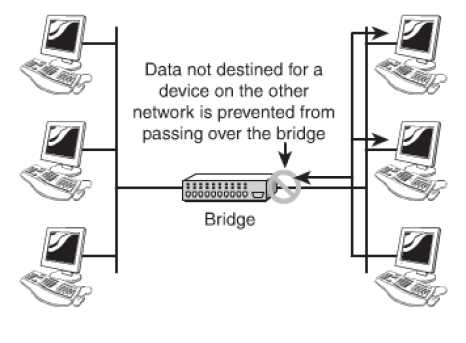
Figure 31: Working of a Bridge
The primary advantage of using a bridge is that it prevents traffic congestion by sending the traffic towards the destination MAC address. They also allow isolation of networks. It is always recommended that consideration be paid to placement of the bridge and bridging loops before incorporating them in a network.
Types of Bridges: Three types of bridges are in networks. They are:
- Transparent Bridge: This Bridge is not visible to other devices that are present on the network. It only blocks or forwards the data based on the MAC address. These are the most commonly used of all the types of bridges.
- Translational Bridge: This Bridge translates the data that it receives. It can easily convert from one networking system to another. They are best suited when two different networks, such as Ethernet and token ring networks are to be connected.
- Source-Route Bridge: These have been specially designed by IBM for token ring networks. The name owes its origin to the fact that the entire route of the frame is embedded within the frame. This facilitates the decision making process regarding forwarding of the frame through the network. As the use of token rings is declining, so is the use of this type of bridge.
Routers: Routers are a common feature of networks of today and are used in networks varying from small home offices to corporate spread over remote sites. These are devices that do the job of directing data around the network. As the data arrives, the router determines its destination of the data and determines the best way for the data to travel. The software configured network addresses are used by the router for determining the destination. They prove better than bridges and switches when it comes to functioning. All this also makes them more complex. A router needs minimum two network interfaces. The figure given below illustrates the working of a router.
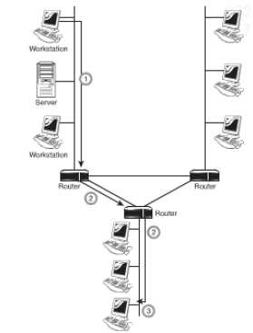
Figure 32: The basic function of a router
A router can be installed as a dedicated hardware device or as a server system.
Dedicated Hardware Routers: They offer greater levels of performance than the server based. The limitation with these is that they have only limited features as compared to their costs. The advantages of using these routers are:
- Their performance in terms of speed is good;
- They are reliable than server-based routers;
- When it comes to efficacy against attacks they are better than the server-based routing solutions.
The disadvantages of these routers are:
- They are not pocket friendly;
- They need specialized and trained staff to manage them;
- Their use is limited.
The features of the router determine the capabilities of the same. Where a basic router may route only one protocol between two networks interfaces of the same type; an advanced router may act as a gateway between two networks and two protocols. Features like firewall services, remote access functionality, security and authentication may also be provided.
Gateways: The term gateway is used to describe any device, system or software application that can do the function of translating data from one particular format to another. It converts the format of the data without doing anything to the data itself. It can be used in multiple ways. To exemplify, a translation bridge is a gateway, a router that routes data from an IPX network to an IP network is also a gateway. Systems like Microsoft Exchange or Novell GroupWise, used by some offices, transmits mail in a certain format internally and when the mail has to be sent to a user outside the system it is converted to a different format. The conversion process is done by a software gateway. A gateway resides between the client PC and the mainframe. The figure given below illustrates the working of a gateway.
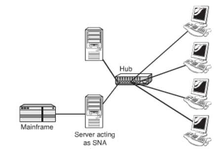
Figure 33: An SNA Gateway
Modems: The word modem is a contraction of the words modulator and demodulator. Modems are not use for very complicated functions. They perform the job of translating digital signals from a computer into analog signals. The advantage of this conversion is that these signals can travel across conventional phone lines. It works by modulating the signal (at the sending end) and demodulating the same (at the receiving end).
Modems compromise on the speed and are a slower means of communication. They work well for browsing pages or downloading small files but are unsuitable for bigger files. Modems are available as internal devices as well as external devices. The AT commands are used for configuring, controlling and diagnosing a modem. The most commonly used AT commands are:
ATA: Answers an incoming call;
ATH: Hangs up the current connection;
ATZ: Resets the modem
ATI3: Displays modem identification information
Modem Connection Speeds: The actual speed of a modem connection is controlled by multiple factors like the quality of the line, and the speed of the modem, the speed of the Universal Asynchronous Receiver/Transmitter (UART) The UART chips used today work at speeds in excess of those offered by modems. The table below illustrates the various UART chips and their associated speeds.
|
UART |
Chip Speed (bps) |
|
8250 |
9,60 |
|
16450 |
115,20 |
|
16550 |
115,20 |
|
16650 |
430,800 |
|
16750 |
921,00 |
|
16950 |
921,600 |
Table 1: UART and the Corresponding Chip Speeds
Modem speeds are expressed in baud rate or bits per second (bps). Baud rate is the number of times a signal changes in each second and the bps rate is the number of bits of data that can be sent or received in a second. The higher the bps rate is the better is the performance of the modem. Baud rates and bps rates are not always identical. Standards have been created to define the data throughput of the modem and are referred to as V standards.
Network Interface Cards (NIC's): By using NIC's which come in all shapes, sizes and budgets, computers are connected to the network. The type of NIC to choose depends on factors like network compatibility, bus compatibility, port compatibility and hardware compatibility. Network Interfaces are of two types: - Add in Expansion Card (PCMCIA): These are not in built into the computer and have to be incorporated. The types and the installation of these cards are discussed in detail below.
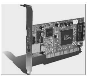
Figure 34: An Expansion NIC
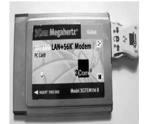
Figure 35: A PCMCIA NIC
There are minimum two LED's on the network interface to indicate specific conditions.
In some network cards, there may be no lights at all or the functions of certain lights are
combined and color code is used to represent various conditions. The figure given below
illustrates a situation where the lights are incorporated into the media adapter.
These LED's are:
- Link light: The network connection between the card and the network are indicated by this LED and an unlit link light means that the network cable or connection is not proper.
- Activity light: The network activity is indicated by this LED. The light flickering often is an indicator of normal conditions; constant flickering indicates a busy network. Constant flickering also indicates that there could be a problem in the network which needs to be investigated.
- Speed light: The speed of the network is indicated by this LED. Ethernet NICs usually have this feature.
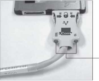
Figure 36: Indicator lights on a media adapter for a PCMCIA NIC
Installing Network Cards: The following points need to be considered while installing network cards:
- Drivers: It is almost certain that an NIC is supplied with a driver disk, but has to be checked is that is the driver latest. It is also important to ensure that the driver is installed and configured properly.
- NIC Configuration Utilities: In the initial days NIC's were configured with jumpers (small groups of pins) or dip switches (small plastic blocks of switches). These were an efficient method to configure but lost preference over the software configuration utilities. The software configuration utility configures as well as tests the working of the card.
- System Resources: For the proper functioning it is necessary for the NIC to have certain system resources allocated. These resources are: the interrupt request (IRQ) and memory addresses. Manual assignment of values may be needed to be done in some cases. In most instances, it is plug and play, that is, resources for devices are assigned automatically.
- Physical Slot Availability: There are multiple expansion slots available on a PC. The newer systems are more likely to have built in devices meaning that valuable slots are left free, but in case of older systems there may be a shortage of slots.
- Built-in Network Interfaces: In a built in network interface, the same is embedded on the mother board of the system. The advantages of this are; the expansion slots are free, hardware compatibility is definite. The disadvantage is that the built in component does not leave any chances of up gradation.
Media Converters: It is a part of the job of a Network Administrator to find means to increase network performance in a pocket friendly manner. Demands of high speed networks and networks spread over large distances, assimilating newer technology with the older further stand as challenges in front of the administrators. These challenges can be effectively dealt with by the use of Network Media Converters.
Media Converters are used for interconnecting cables which are of different types in an existing network. They are effective when it comes to combining networks, increasing their flexibility, keeping a check on the cost factor while assimilating the new with the old. Media Converters are available in different shapes and sizes and can be designed to work with Asynchronous Transfer Mode (ATM), Ethernets, Fast Ethernets, Gigabit Ethernet, etc.
Firewalls: Firewalls are an integral part of network design in today's times. It is a network device and can be software or hardware based. It is responsible for controlling access to the network. This helps to keep a check on the outside threats and as a result the data and the resources are better protected. IT is best to place firewalls on the points of entry and exit of the network. Firewalls can also be used to control access between two specific points on the same network.
- Software Firewalls: These are implemented using NOS (Network Operating Systems) such as Linux and Windows servers. Once configured it allows only certain type of traffic to move in. For smaller set ups, a firewall is installed on the local system.
- Hardware Firewalls: Hardware firewalls are dedicated devices that can be easily configured to offer protection from the outside sources. It is used in combination with other devices. They are used in both small as well as large networks.
DHCP Server: The full form of DHCP is Dynamic Host Configuration Protocol. This is the easiest way of assigning TCP/IP information to client systems. Protocol is the method adopted by computers to communicate amongst themselves. Specific settings need to be ensured for a system to enable a system to connect to the network. Computers that are using TCP/IP need to have an IP address to be recognized on the network.
An IP address consists of four octets, or four sets of 8 bit. The decimal form is used to represent it, for example, 192.168.2.1. It is a unique number that is assigned to a PC and it must be within a certain range to allow the PC to connect to other systems. The time of entering IP addresses manually into the network settings are long past. These are known as manual or static IP addresses. Manual IP addresses prove a challenge for the simple reason that they are time consuming and have to be kept unique as duplication of the address prevents successful connection to the system that was allotted the address at the first stage. In larger networks this is all the more a daunting task as computers are moved, replaced or even taken out of the network system. In such situations the DHCP plays an important role.
The DHCP performs the function of assigning IP addresses automatically; as a result the administrator is not required to do this job. With a DHCP server on the network, the workstation boots up, request for an IP address is issued to the server and the server responds by issuing an IP address, the receipt of the address is acknowledged by the workstation. As the address is issued for sometime it is known as a lease. The workstation now has all the information that it requires to be a part of the network.
Because of their ability to act automatically, DHCP servers are preferred in client/server setups. The likelihood of more than one DHCP server in an environment is also common.