Section 1.2: Identifying Motherboard Components
The motherboard is the backbone of a computer because the components of a motherboard provide basic services needed to run a computer. It is most important component of a computer because it connects all other components of a computer together. It provides a platform to connect devices such as disk drives, CPU sockets, memory ports and other types of expansion slots. It also contains CPU, underlying circuitry, video components, RAM slots and a variety of other chips. The motherboard is made of green or brown fiberglass and is placed at the bottom or the side of the computer case.
Some motherboards have peripheral devices such as video, sound, and networking devices built in. These motherboards are called integrated system boards. These boards are cost-effective because they don't use separate components. However, these built-in components can be disabled through BIOS Setup if they malfunction or need to be replaced.
Some of the motherboard components that provide basic functionality to the computer are discussed below.
Section 1.2.1: Memory Slots
Memory slots contain RAM or memory chips on them. Each memory module differs in chip placement and number of conductors, or pins. Memory modules can be 30 pin, 72 pin, 168 pin, and 184 pin. The number of pins affects the size of the memory slot.
These memory chips contain a small circuit board on them. These circuit boards can be of different types. These types are:
- SIMM (Single Inline Memory Modules): The SIMMs utilizes memory chips on a single side. They are available in two sizes, 30 pin and 72 pin, as shown in Figure 2.
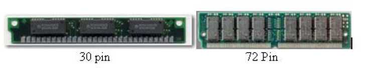
Figure 2
- DIMM (Dual Inline Memory Modules): DIMMs utilize memory chips on both the sides of a circuit board. They are used in modern systems, which are Pentium or higher. They usually have 168 pins and are 64 bits in length, as shown in Figure3:
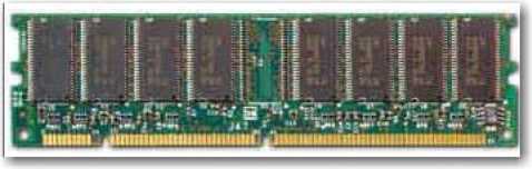
Figure 3
- RIMM (Rambus Inline Memory Module): RIMM contains high speed type of RAM also called Rambus Dynamic RAM (RDRAM). It is quite similar to DIMM except that it has 184 pins and it is slightly longer in size.
- SoDIMMs (Small Outline DIMMs): SoDIMMs are a smaller alternative to a DIMM and are almost half the size of regular DIMMs, as shown in Figure 4.
They are often used in systems which have space restrictions such as laptops.
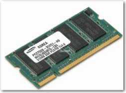
Figure 4
The number of memory slots is different in each motherboard but the appearance of the different slots is same. All the memory slots have metal and plastic tabs on both the sides to keep the memory module safe in the slot. The metal pins at the bottom of the slot make contact with the soldered tabs on each memory module.
Section 1.2.2: CPU (Central Processing Unit or Processors Slots)
The CPU slot allows the CPU to fix itself on the motherboard and use the other components of the system. The different types of processors use different types of CPU connectors. In past the CPU slot used to be a rectangular box called a PGA (Pin Grid Array) socket. The socket had many holes to accommodate the pins on the bottom of the chip. However now a days, the CPU slot has taken on several different forms. The new CPU slots have additional holes to hold new and more powerful chips.
With the release of PENTIUM II, the architecture of the slot has changed from rectangular to more of an expansion slot style called SECC (Single Edge Contact Cartridge). This includes Slot 1 and Slot 2 for Intel CPUs and Slot A for Athlon (AMD) CPUs. Instead of having pins or using a standard PGA package, SECC uses goldfinger contacts, which the processor uses to carry its signals back and forth.
The table below shows the socket types, the number of pins they have, and the types of processors they support.
|
Name |
Interface |
|---|---|
|
Socket 1 |
169-pin |
|
Socket 2 |
238-pin |
|
Socket 3 |
237-pin |
|
Socket 4 |
273-pin |
|
Socket 5 |
320-pin |
|
Socket 6 |
235-pin |
|
Socket 7 |
321-pin |
|
Socket 8 |
387-pin |
|
SECC Type U Slot 1 |
242-way connector |
|
SECC Type U Slot 2 |
330-way connector |
|
Slot A |
242-way connector |
|
Socket 370 |
370-pin |
|
Socket A |
462-pin |
Description
Found on 486 motherboards and support 486 SX/SX2, 486 DX/ DX2, and 486 DX4 OverDrive.
A minor upgrade from Socket 1. Supports 486 SX/ SX2, 486 DX/ DX2, and 486 DX4 OverDrive. Additionally support a Pentium OverDrive.
The last of the 486 sockets. Supports all of the Socket 2 chips in addition to 5x86.
Supports only the low-end Pentium-60/66 and the OverDrive chip.
Supports Pentium class chips from 75MHz - 133MHz. Supports Pentium 75+ Overdrive
Used with 486 CPUs. Supported DX4, 486 Pentium Overdrive. Supported Pentium 75-200, Pentium 75+ Overdrive.
Used exclusively by the Intel Pentium Pro.
Used by Intel Pentium II Used by Intel Pentium III
AMD interface mechanically compatible with Slot 1. Used by Athlon CPU.
Used by Pentium III Coppermine and Tualatin CPUs in variants known as FC-PGA and FC-PGA2 respectively.
AMD interface introduced with the first Athlon processors (Thunderbird) with on-die L2 cache. Subsequently adopted throughout AMD's CPU range.
|
Socket 423 |
423-pin |
Used by Pentium 4 |
|---|---|---|
|
Socket 603 |
603-pin |
The connector for Pentium 4 Xeon CPUs. |
|
Socket 478 |
478-pin |
Used by Pentium 4 and Celeron 4. |
|
Socket 754 |
754-pin |
AMD's 754-pin CPU interface form factor introduced with its 64-bit Athlon 64 processor. |
|
Socket 940 |
940-pin |
Used by some versions of Athlon 64 and Opteron |
|
Socket 939 |
939-pin |
Used by some versions of Athlon 64. |
|
LGA775/ Socket T |
775-pin |
Used for some Pentium 4, Pentium D, Core 2 Duo, and Core 2 Quad CPUs. |
|
Socket AM2 |
Came to replace AMD for the Socket 939 and Socket 754. | |
|
940-pin |
Offers support for an array of processors and DDR2 RAM, used by Athlon 64 family. | |
|
LGA771/ Socket J |
771-pin |
Supports the Dual Core Xeon Dempsey and Woodcrest, Quad Core Clovertown, and Core 2 Extreme processors. |
|
Socket F |
1207-pin |
Suppors AMD's native quad core Opteron processors and DDR2 RAM. |
Section 1.2.3: Power Connectors
The power connectors are used to connect the mother board to the power supply. The ATX type has a single power connector having a block of 20 holes in 2 rows and on an AT type of motherboard there is a single block of 12 pins covered by 2 connectors with 6 holes each.
Section 1.2.4: On-board Floppy and IDE connectors
The disk drives are connected to motherboard through drive interfaces. There are two primary types of drive interfaces called floppy drive interfaces and IDE interfaces. The floppy drive interfaces allow a floppy disk drive to connect to the motherboard and the IDE interface allow the hard disks, CD drives, and other IDE based drives to connect to the mother board. When these interfaces are integrated in the motherboard, they are called on-board whereas if they are used as an expansion card, they are known as off-board. The interface consists of circuitry and a port. Some motherboards also have SCSI interfaces that can be used to connect drives.
Section 1.2.5: Battery
A small battery is located on the motherboard to keep the settings such as date, time, and hard drive configuration updated in memory. The PC stores these settings and the BIOS information in a special memory chip called CMOS chip. This chip requires constant power to retain the information it stores. The battery provides power to CMOS chip so that it can retain information.
Section 1.2.6: Jumpers and Dip Switches
Jumpers and Dip switches are used to configure various hardware options on the motherboard. The jumpers consist of a set of small pins, which can be covered with a small plastic box that connects the covered two pins together to allow the flow of electricity between them, as shown in Figure 5.
Jumper
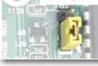
Figure 5
Placing a jumper block over another set of separate pins, allows you to close an electrical circuit at a certain sections of the circuit board. A particular jumper setting makes its possible for the BIOS settings to be retained or removed. Jumpers are used to configure computer peripherals such as Hard Drives, Modems, Sound Cards, and various other components.
Dip switches perform the same function as jumpers with on/off switches. They can be turned to the ON or OFF to configure computer peripherals, as shown in Figure 6:
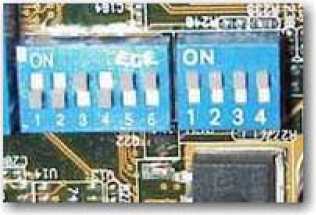
Figure 6
Section 1.2.7: System Board Form Factor
The form factor of a motherboard refers to the general shape and size of a motherboard. It also specifies the type of case (metal or plastic box) in which the internal components
will be installed and the power supply that will be supported. Form factor of the motherboard helps you to purchase the correct case and components for your mother board if you are building your PC yourself.
A number of Motherboard Form Factors have been in existence. These Form Factors are:
- AT & Baby AT: This form factor is found in 386 Class or earlier computers. It was big in size (12" wide) and therefore caused the overlap problems with space required for the drive bays. To overcome this issue, the Baby AT form factor was introduced with 8.5" width, as shown in Figure 7. It contained sockets for peripheral devices such as the keyboard, mouse, and on circuit board and memory sockets at the front of the motherboard. As processors became larger, the Baby AT form factor did not allow for space to use a combination of processor, heatsink, and fan.
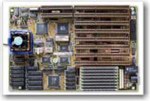
Figure 7
- ATX: This for factor was introduced to remove the issues raised in Baby AT. It was more integrated and defined standard locations for the keyboard, mouse, I/O, and video connectors, as shown in Figure 8. It helped in reducing the overall size of the computer because it placed expansion slots onto separate riser cards that could be plugged into the motherboard. It offered many improvements in design specification such as the use of a single 20-pin connector for the power supply, integrated I/O Port connectors soldered directly onto the motherboard, and less overlap between the motherboard and drive bays. It is the most widely accepted industry standard. However, legacy AT systems are still widely in use.
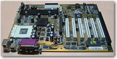
Figure 8
- Micro-ATX: MicroATX followed the ATX form factor and offered the same benefits. It however, brought an overall system design improvement and costs reduction by reducing the physical size of the motherboard. It offered a reduced number of I/O slots on the board, more I/O space at the rear, and reduced emissions from using integrated I/O connectors.
- LPX: This is a non-standard proprietary form factor found in low-profile desktop cases with a riser card arrangement for expansion cards. It has sound and video integrated onto the motherboard, expansion boards run parallel to the motherboard, and a limited number of expansion slots. This is inexpensive but generally difficult to repair and upgrade due non-standardization. It also offers poor cooling.
- NLX: It is updated LPX. It is an actual standard that has options for upgrading and repair. It offered support for larger memory modules, tower cases, AGP video support and reduced cable length.
- BTX (Balanced Technology Extended): This was totally different from its predecessors and is the form factor that takes advantage of technologies such as Serial ATA, USB 2.0, and PCI. Besides this form factor is smaller than microATX systems, provides an increased number of system slots, uses in-line airflow which reduces the number of fans needed in the system, and provides a better component placement for back panel I/O controllers.
Section 1.2.8: I/O Interfaces
The Input-output (I/O) interfaces allow a computer to communicate with other external devices. They are physical elements on the computer that allows data exchange.
Section 1.2.9: Universal Serial Bus (USB)
USB is a plug-and-play interface that allows high-speed connection between a computer and other devices, such as keyboards, telephones, digital cameras, scanners, and flash drives. It was developed by Intel in collaboration with Compaq, IBM, DEC, Microsoft, NEC, and Northern Telecom.
The hot-swapping feature of USB has made it very useful. It allows you to add or remove a new device to your computer without the need to turn off the computer and without having to add an adapter card. The two USB specifications are as follows:
- USB 1.0: This specification was introduced in 1996. It made the connectivity of external devices to PCs easier and simplified the software configuration of devices. The original USB 1.0 specification had a data transfer rate of 12 Mbit/s.
- USB 2.0: This is a Hi-Speed specification created in 2002, as shown in Figure 9. It provides greater enhancement in performance and is up to 40 times faster than USB 1.0. It provides a data transfer rate of up to 480 megabits per second (Mbps).
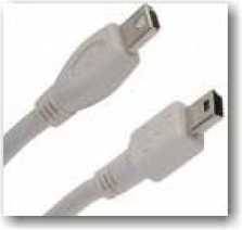
Figure 9
Section 1.2.10: IEEE 1394/ Firewire
Firewire is also an interface just as USB for connecting devices to your personal computer, as shown in Figure 10. It is based on IEEE 1394 serial bus electronics standard that provides a single plug-and-socket connection and allows up to 63 devices to be connected to it. It allows data transfer speeds up to 400 Mbps. Just like USB, it also offers hot-plug and plug and play capability that allows you to add/remove devices to/from your computer without disrupting its activities.
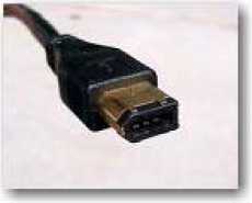
Figure 10
The multi-platform serial bus FireWire port became common in 1995, when Apple, Inc. introduced digital camcorders with a FireWire port on it. Today, the FireWire port is used on a number of other devices.
Although both USB and FireWire appear same, the most significant technical difference between them is that USB uses a "speak-when-spoken-to" protocol. This means that the USB devices cannot communicate with the host unless the host specifically requests communication. The FireWire device on the other hand can communicate with any node at any time on a network. Also even though both are theoretically similar in their maximum transfer rate, FireWire 400 has performance advantage over USB 2.0. USB was designed for simplicity and low cost, while FireWire was designed for high performance, particularly in time-sensitive applications such as audio and video.
Section 1.2.11: Serial I/O (RS232)
RS-232 is a standard for serial ports. This standard has become so popular that it is interchangeably used for serial ports. RS-232 was that first standard that enabled a computer to communicate with external devices. It is called serial I/O because it sends data through a single wire serially, which means the bits are sent one after the other, as shown in Figure 11:
Computer 1 | Computer 2
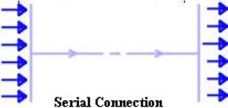
Figure 11
Initially, the serial ports could only send data. However, soon two-way serial ports came into existence that could send as well as receive data. These ports therefore have two wires, one to send data and the other to receive it. The data in serial ports is sent at random intervals asynchronously. Each character is represented by 8 bits, which are sent is succession. The serial communication requires control bits that start and end the communication. Each character is preceded by a START bit and followed by a STOP bit.
The Serial ports generally have 9 or 25 pins and are built into the mother board, as shown in Figure 12. Serial connectors generally use the DB9 and DB25 connectors for 9 and 25 pins respectively. All Intel PCs have one or two serial ports usually referred to as Com1 and Com2.
Section 1.2.12: Parallel Port
Unlike serial ports, the parallel port sends data simultaneously on several channels or wires. They can be used to send 8 bits, one octet simultaneously via 8 wires, as shown in Figure 13:
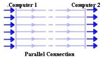
Figure 13
Parallel Connection
Initially the speed offered by parallel ports was of 2.4Mb. However, later Enhanced parallel ports (EPP) and Enhanced Capabilities Port (ECP) were developed to achieve higher speeds of 8 to 16 Mbps. Parallel ports, like serial ports, are built into the mother board and use DB25 connectors allow connection to external devices, as shown in Figure 14:
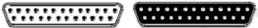
Figure 14
Section 1.2.13: Network Interface Card
A network card or a Network Interface Card (NIC) is a network interface between a computer and a network cable that allows a computer to send and receive data to/from a network. The NIC prepares, sends, and controls data on the network. The NIC uses transceiver to prepare data. It translates data sent by the computer into a form that is understandable by the network cable, transfers that data to another computer, controls the dataflow, and finally translates the data coming from the cable into the form that is understandable by the computer.
Each NIC has a unique MAC address that identifies it on a network. The MAC address is assigned to the NIC by the card's manufacturer and is unique in the world. A network card usually has two indicator lights (LEDs). Green light indicates the flow of electricity and the red/orange light indicates the flow of data, as shown in Figure 15:
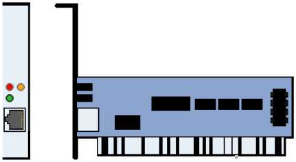
Figure 15
Section 1.2.14: PS/2
The PS/2 interface is an interface that allows a PC to connect to a PS2 mouse and a keyboard. It was introduced in 1987 by IBM for its PS/2 desktop PC. The PS/2 connector has a 6-pin Mini-DIN plug and socket, as shown in Figure. They are available in two sizes, 1/4 inch diameter and 3/8 inch diameter. The smaller size is more common, but adapters are available to convert one size to the other, as shown in Figure 16. Although, both keyboard and mouse interfaces are electrically similar, they cannot be used interchangeably.
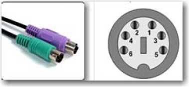
Figure 16
Recently USB connector has largely replaced the use of the PS/2 connector, especially for a mouse.
Section 1.2.15: Sound card
A sound card or an audio card allows a computer to send and receive audio signals. They are used to provide the audio component to multimedia applications such as music composition, education, and games. Some computers have sound card built in on the motherboard, while others require additional expansion cards to provide for audio capability. They use an ISA or PCI interface to connect to the motherboard A sound card appears, as shown in Figure 17:
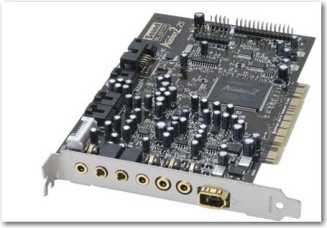
Figure 17
The sound cards convert the digital signals from the computer to analog signals so that we can hear them. It also converts analog signals to digital signals when you use mike for digital recordings or data transfer. It therefore works as a digital-to-analog converter (DAC) and analog-to-digital converter (ADC). Instead of separate ADCs and DACs, some sound cards use a coder/decoder chip, also called a CODEC, which performs both functions.
Section 1.2.16: Video Card
A video card, video adapter or a graphics card is an expansion card that output the images generated by the CPU, as shown in Figure 18. It is basically a piece of hardware that takes that input from CPU and tells the monitor which of the dots on the screen to light up in what color to allow you to see it. Many video cards offer added functions, such as accelerated rendering of graphics, video capture, and running PC games
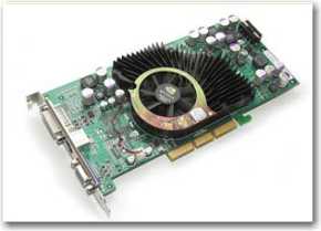
Figure 18
Video card these days have become quite advanced. They have their own intelligence and do a lot of processing that would otherwise have to be done by the system processor. Its quality and efficiency also impacts the system performance. For example, high graphics games depend on the video card for a high frame rate than by the system CPU. Starting with the MDA in 1981, several video cards were released. Among them VGA is widely accepted. It was later developed into the SVGA (Super VGA) standard, which reached 2 MB of video memory and a resolution of 1024x768 at 256 color mode.
Section 1.2.17 Modem
A modem is a device that modulates an analog carrier signal to encode digital information, and also demodulates a carrier signal to decode the transmitted information. It allows a computer to transmit data over telephone or cable lines. It converts the digitally stored data on computer to analog data so that it can be transmitted over telephone and also converts the analog data to digital data so that it can be understood by computers. Modems follow the RS-232 interface to connect with computers, as shown in Figure 19:
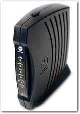
Figure 19
They can either be classified by the amount of data they can send per second or by Baud (the number of times the modem changes its signal state) per second.
Section 1.2.18: BUS Architecture
The supporting circuitry of the system that allows the processor to communicate with the rest of the system is called bus. The bus transfers data between computer components inside a computer or between computers. When computers were first introduced they only had one bus, and all the devices such as memory, graphics cards, and IO (Input/Output) ports used to attach to this single bus. However today, a motherboard has several buses for each memory, expansion cards, and high data transfer devices. Each bus has its own speed and width.
There are two major types of buses, Expansion Bus and the Local Bus. The main purpose of the expansion bus is to connect various types of devices to the CPU and the Local bus allows the devices that require high data transfer rates to directly connect to the CPU. The expansion buses can be divided into internal and external buses. The external buses include ports such as Serial, Parallel, USB, FireWIre and Infrared and the Internal buses include buses such as:
- ISA (Industrial Standard Architecture): This is a 16 bit or 8 bit bus used in old computers, as shown in Figure 20. It operates at a clock speed of 8 MHz and required separate system resources for each ISA device. Because this is an old technology the latest motherboards do not have slots for it.
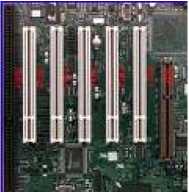
Figure 20
- PCI (Peripheral Component Interconnect): This is the fast 32 or 64 bit bus that operates at the 33 MHz - 66MHz (Pentium) speed, as shown in Figure 21. This is used in most motherboards these days. Its slots are typically white. It allows PCI devices to share IRQ and other system resources.
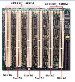
Figure 21
- AGP (Accelerated Graphics Port): This is also very fast 32 or 64 bit bus that operates at the 66 MHz speed. These buses are developed to meet the needs to PC games that need fast speed, better graphics, and more realism. Its slots are usually brown and usually only one slot is available on a motherboard and it is exclusively used for video card, as shown in Figure 22:
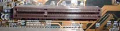
Figure 22
- PCIE (PCI Express): This bus is based on PCI system and uses a network of serial interconnects that operate at high speed. Most existing systems can be easily converted to PCIE and it is actually a replacement of PCI and AGP. It operates at different speed levels 1X, 2X, 4X, 8X, 16X, and 32X, as shown in Figure 23:.
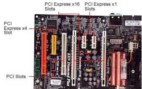
Figure 23
- AMR (Audio Modem Riser) and CNR (Communications Network Riser):
Riser approach is designed to separate out the analogue circuitry to its own riser slot (and board) so that the cost of the function is reduced, as shown in Figure 24. The AMR is a mother board riser card and interface that supports both audio and modem functions. The CNR on the other hand is a mother board riser and interface that supports the audio, modem, and local area network (LAN) interfaces of core logic chipsets.
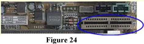
Figure 24
- PCMCIA (Personal Computer Memory Card International Association):
The PCMCIA is an industry organization that has developed standards for PC cards formerly known as PCMCIA cards. The PC Cards are known for their thinness therefore they are best suited for laptop computers. All the PC Cards have the same width and length but they vary in thickness. Due to this they are divided into following three types: - Type1 : These are 3.3 mm thick and are primarily used for adding additional ROM or RAM to a computer.
- Type2 : These are 5.mm thick and are used for adding modem and fax modems.
- Type3 : These are 10.5 mm thick and are used for adding portable disk drives
- RAID 0: striping: In this level the data is written across multiple drives for fast read and write access, as shown in Figure 27. RAID 0 offers superior I/O performance, which can be increased further by using multiple controllers. This is technically not considered RAID because it does not provide fault tolerance.
- RAID 1: mirroring: In this level the data is written on two or more disks to achieve fault tolerance. If a disk fails, another data drive or the mirror drive can be used for data recovery and the work continues. The main disadvantage however is that only half of the total disk capacity is used because all data get written twice, as shown in Figure 28. You need at least 2 disks for a RAID 1 array.
- RAID 5 striping with parity: This level combines the benefits of both RAID 0 and RAID 1. It uses a parity disk that is distributed across all the drives in an array in addition to striping the data across them, as shown in Figure 29. A RAID 5 array can withstand a single disk failure without losing data or access to data.
- Northbridge: This set of chips connects the CPU to very high-speed devices such as main memory and graphics controllers.
- Southbridge: This set of chips connects the CPU to lower-speed peripheral buses (such as PCI or ISA). It may also contain some on-chip integrated peripherals, such as Ethernet, USB, and audio devices.
Section 1.2.19: PATA/ IDE/ EIDE
PATA (Parallel ATA) drives are one of the most commonly used earliest drive types, which have been a standard for hard drives for more than a decade. PATA drives are available in standard sizes of 2.5 and 3.5 inch and have data transfer speeds of up to 133 MB/s, as shown in Figure 25. PATA allows up to 2 internal devices per drive channel. Recently PATA is replaced by the SATA (Serial Advanced Technology Attachment) hard drives.
The PATA drives are also known as Integrated Drive Electronics (IDE). As the name implies, the IDE drives have HDD controller integrated in them and they use a relatively short ribbon to connect the drive/controller to the IDE interface. The IDE drives have 40 pins and support the connection transfers rate of 16 bits of data at a time on the data cable.
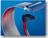
Figure 25
IDE was unofficial updated to EIDE by Western Digital to use direct memory access (DMA) to transfer data between the disk and the computer. However, the improvement was later made an official ATA standard.
A typical motherboard has two IDE connectors and each of them can support up to two drives on the same cable. This means you can have up to four IDE devices per system. Each IDE drive has one master drive on it. If there are two drives then one of them should be master and the other should be slave. This is because the IDE controllers are integrated into the drives and they need to share the same IDE interface. The controller on the master drive also controls the data transfer of the slave drive.
Section 1.2.20: SATA and eSATA
With the advent of SATA (Serial Advanced Technology Attachment) drives PATA drives are no longer used. Normally, parallel devices are supposed to be faster than serial devices but in this case serial device SATA is much faster than parallel PATA. It offers a speed of 600 MB/sec as compared to the speed of 133MB/sec offered by PATA. SATA uses four long narrow cables (1 meter), two for sending and two for receiving data, which is quite convenient to handle because it avoids congestion, as shown in Figure 26. SATA supports full duplex data transfer and also supports 'hot swap' facility.
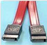
Figure 26
The External Serial Advanced Technology Attachment (eSATA) is an external interface for SATA technologies. It provides fast data transfer speeds for external storage devices with a triple transfer rate as provided by USB 2.0 and FireWire 400. This is because eSATA does not have to translate data between the interface and the computer. However, it requires its own power connector. If you need to use eSATA in desktop motherboards, you need to purchase a PCI card that supports an eSATA interface.
Section 1.2.21: RAID (Redundant Array of Inexpensive Disks)
RAID is a technology that allows you to combine the power of more than one disk to increase the performance and reliability of data storage. RAID can be done with SCSI, IDE, SATA or FC drives. RAID has different levels. Some of the popular RAID levels are:
Raid D
|
T |
f | |
|---|---|---|
|
Block 1 |
Block 2 | |
|
Block 3 |
Block 4 | |
|
Blocks |
Blocks | |
|
Block 7 |
Blocks | |
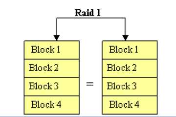
Figure 28
Raid 5
|
__ Block 1 |
__ Block 1 |
__ Block 1 |
__ Parity | |||
|---|---|---|---|---|---|---|
|
Block 2 |
Block 2 |
Parity |
Block 2 | |||
|
Block 3 |
= |
Parity |
Block3 |
= |
Block 3 | |
|
Parity |
Block 4 |
Block 4 |
Block 4 |
Figure 29
Section 1.2.22: Chipset
A chipset is a group of integrated circuits, or a set of specialized chips on a computer's motherboard that are designed to work together and are marketed as a single product. There is two specific pair of chips on the motherboard, as shown in Figure 30. These chips are:
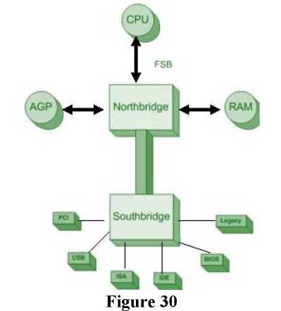
Figure 30
The performance of a system largely depends on the chipset because it controls communications between the processor and external devices. A chipset is usually designed to work with a specific family of microprocessors.
Section 1.2.23: BIOS/ CMOS
The CMOS or BIOS settings are the Basic Input Output settings that you can set through a setup program that can be accessed by pressing the designated key at the startup. The most common settings include port settings, drive types, boot sequence, date time, and virus /security settings.
The CMOS setup also allows you to set a supervisor password that effectively locks user from making changes to the computer. If however, you forget the password after setting it, you need to remove the CMOS battery to reset everything. You may also reset everything by resetting the Rest jumper on the motherboard.
Section 1.2.24: Firmware
Any software built into hardware is called a firmware. For example, the software built in to the laser printer that controls it and allows you to interact with it at the console.
Section 1.2.25: Daughterboards
The boards that are added to motherboards to add its functionality are called daughterboards. The common implementation is the use of daughterboards to insert expansion cards to the motherboards.