9.5 Label imposition/disposition
9.5.1 Creating the (Inner) VPN Label
The inner label identifies the outgoing interface out which the egress PE should forward the unlabeled packet. This inner label, called the VPN label, must be allocated for each route added to each customer VRF. More specifically, a customer CE will advertise routes to the PE, with the PE storing those routes in that customer's VRF. In order to prepare to forward packets to those customer subnets, the PE needs to allocate a new local label, associate the label with the prefix (and the route's next-hop IP address and outgoing interface), and store that information in the LFIB.
The figure below shows PE2's routes for 10.3.3.0/24 in both VRF-A and VRF-B and the resulting LFIB entries. The figure shows the results of PE2's process of allocating a local label for each of the two routes and then also advertising those labels using BGP. (Note that the LFIB is not a per-VRF table; the LFIB is the one and only LFIB for PE2.)
9.5.2 Creating the VPN Label on the Egress PE
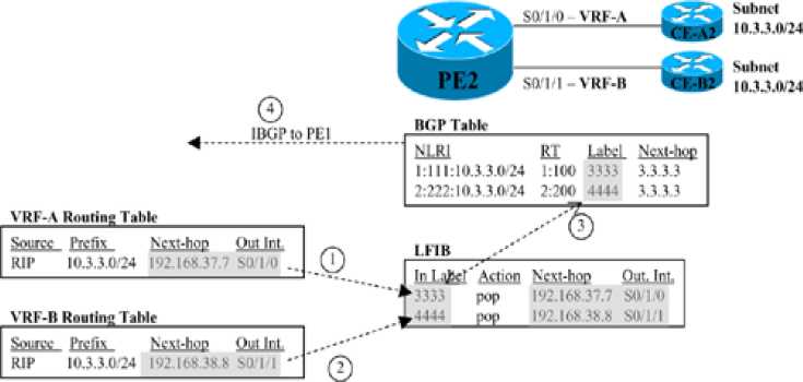
The steps shown in the figure are as follows:
1. After adding a route for 10.3.3.0/24 to VRF-A, PE2 allocates a local label (3333) to associate with the route. PE2 then stores the local label and corresponding next hop and outgoing interface from VRF-A's route for 10.3.3.0/24 into the LIB (not shown) and LFIB.
2. PE2 repeats the logic in Step 1 for each route in each VRF, including the route in VRF-B shown at Step 2. After learning a route for 10.3.3.0/24 in VRF-B, PE2 allocates a different label value (4444), associates that route's next-hop IP address and outgoing interface with the new label, and adds the information to a new LFIB entry.
3. PE2 adds the local labels to the BGP table entry for the routes, respectively, when redistributing routes into BGP.
4. PE2 uses IBGP to advertise the routes to PE1, with the BGP Update including the VPN label.
As a result of the first two steps in the figure, if PE2 receives a labeled packet and analyzes a label value of 3333, PE2 would be able to forward the packet correctly to CE-A2. Similarly, PE2 could correctly forward a received labeled packet with label 4444 to CE-B2.
9.5.3 Creating LFIB Entries to Forward Packets to the Egress PE
The outer label defines the LSP from the ingress PE to the egress PE. More specifically, it defines an LSP used to forward packets to the BGP next-hop address as advertised in BGP Updates. In concept, the ingress PE adds the outer label to make a request of the core of the MPLS network to "deliver this packet to the egress PE-which advertised this particular BGP next-hop address."
MPLS VPNs use an IGP and LDP to learn routes and labels, specifically to learn the label values to use in the outer label. To link the concepts together, it can be helpful to think of the full control plane process related to the LSP used for the outer label, particularly Step 4 onward:
1. A PE, which will be an egress PE for this particular route, learns routes from some CE.
2. The egress PE uses IBGP to advertise the routes to an ingress PE.
3. The learned IBGP routes list some next-hop IP address.
4. For MPLS VPNs to work, the PE and P routers must have advertised a route to reach the BGP next-hop addresses.
5. Likewise, for MPLS VPNs to work, the PE and P routers must have advertised labels with LDP for the routes to reach the BGP next-hop addresses.
6. Each P and PE router adds its part of the full end-to-end LSP into its LFIB, supporting the ingress PE's ability to send a packet to the egress PE.
9.5.4 Creating VRF FIB Entries for the Ingress PE
The last part of the data plane analysis focuses on the ingress PE. In particular, the ingress PE will process the incoming packet using the VRF associated with the incoming interface (statically configured), and then forward the packet using that VRF's FIB.
The FIB entry needs to have two labels to support MPLS VPNs: an outer label that identifies the LSP with which to reach the egress PE, and an inner label that identifies the egress PE's LFIB entry that includes the correct outgoing interface on the egress PE. Although it might be obvious by now, for completeness, the ingress PE learns the outer and inner label values as follows:
The outer label is based on the LIB entry, specifically for the LIB entry for the prefix that matches the BGP-learned next-hop IP address-not the packet's destination IP address.
The inner label is based on the BGP table entry for the route in the VRF that matches the packet's destination address.
9.5.5 Penultimate Hop Popping
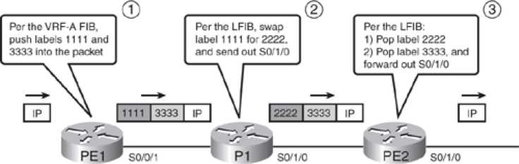
The operation of the MPLS VPN data plane works well, but the process on the egress PE can be a bit inefficient. The inefficiency relates to the fact that the egress PE must do two lookups in the LFIB after receiving the packet with two labels in the label stack.
Two LFIB Lookups Required on the Egress PE
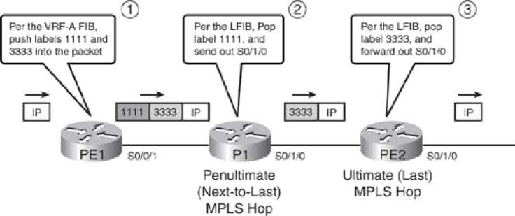
To avoid this extra work on the very last (ultimate) LSR, MPLS uses a feature called penultimate hop popping (PHP). (Penultimate simply means "next to last") So the penultimate hop is not the very last LSR to process a labeled packet, but the second-to-last LSR to process a labeled packet. PHP causes the penultimate-hop LSR to pop the outer label, so that the last LSR-the ultimate hop if you will-receives a packet that only has the VPN label in it. With only this single label, the egress PE needs to look up only one entry in the LFIB.
Single LFIB Lookup on Egress PE Due to PHP
9.5.6 Other MPLS Applications
This section introduces and explains the concept of a Forwarding Equivalence Class (FEC) and summarizes the concept of an FEC as used by various MPLS applications.
For each FEC, each LSR needs a label, or label stack, to use when forwarding packets in that FEC. By using a unique label or set of labels for each FEC, a router has the ability to assign different forwarding details (outgoing interface and next-hop router.)
Each of the MPLS applications can be compared by focusing on the information used to determine an FEC. For example, MPLS traffic engineering (TE) allows MPLS networks to choose to send some packets over one LSP and other packets over another LSP, based on traffic loading-even though the true end destination might be in the same location. By doing so, SPs can manage the flow of data over their high-speed core networks and prevent the problem of overloading the best route as determined by a routing protocol, while barely using alternate routes. To achieve this function, MPLS TE bases the FEC concept in part on the definition of an MPLS TE tunnel.
You can also compare different MPLS applications by listing the control plane protocols used to learn label information. For example, MPLS VPN uses both LDP and MP-BGP to exchange label information, whereas other MPLS applications use LDP and something else-or do not even use LDP at all. The table below lists many of the common MPLS applications, the information that determines an FEC, and the control plane protocol that is used to advertise FEC-to-label bindings.
Control Protocols Used in Various MPLS Applications
| Application | FEC | Control Protocol Used to Exchange FEC-to- Label Binding |
|---|---|---|
| Unicast IP routing | Unicast IP routes in the global IP routing table | Tag Distribution Protocol (TDP) or Label Distribution Protocol (LDP) |
| Multicast IP routing | Multicast routes in the global multicast IP routing table | PIM version 2 extensions |
| VPN | Unicast IP routes in the per-VRF routing table | MP-BGP |
| Traffic engineering | MPLS TE tunnels (configured) | RSVP or CR-LDP |
| MPLS QoS | IP routing table and the ToS byte | Extensions to TDP and LDP |