9.4 Label Format
The MPLS header is a 4-byte header, located immediately before the IP header. Many people simply refer to the MPLS header as the MPLS label, but the label is actually a 20-bit field in the MPLS header. You may also see this header referenced as an MPLS shim header.
Table MPLS Head
| Field | Length (Bits) | Purpose |
|---|---|---|
| Label | 20 | Identifies the portion of a label switched path (LSP). |
| Experimental (EXP) | 3 | Used for QoS marking; the field is no longer used for truly experimental purposes. |
| Bottom-of-Stack (S) | 1 | Flag, which when set to 1, means that this is the label immediately preceding the IP header. |
| Time-to-Live (TTL) | 8 | Used for the same purposes as the IP header's TTL field. |
The 20-bit Label is usually listed as a decimal value in show commands. The MPLS EXP bits allow for QoS marking, which can be done using CB Marking. The S bit is used when packets hold multiple MPLS headers, this bit allows an LSR to recognize the last MPLS header before the IP header. Finally, the TTL field requires a little more examination, as covered in the next section.
9.4.1 The MPLS TTL Field and MPLS TTL Propagation
The IP header's TTL field supports two important features: a mechanism to identify looping packets, and a method for the traceroute command to find the IP address of each router in a particular end-to-end route. The MPLS header's TTL field supplies the same features-in fact, using all defaults, the presence or absence of MPLS LSRs in a network has no impact on the end results of either of the TTL-related processes. MPLS needs a TTL field so that LSRs can completely ignore the encapsulated IP header when forwarding IP packets. Essentially, the LSRs will decrement the MPLS TTL field, and not the IP TTL field, as the packet passes through the MPLS network. To make the whole process work, using all default settings, ingress E-LSRs, LSRs, and egress E-LSRs work as follows:
Ingress E-LSRs- After an ingress E-LSR decrements the IP TTL field, it pushes a label into an unlabeled packet and then copies the packet's IP TTL field into the new MPLS header's TTL field.
LSRs- When an LSR swaps a label, the router decrements the MPLS header's TTL field, and always ignores the IP header's TTL field.
Egress E-LSRs- After an egress E-LSR decrements the MPLS TTL field, it pops the final MPLS header and then copies the MPLS TTL field into the IP header TTL field.
Example of MPLS TTL Propagation
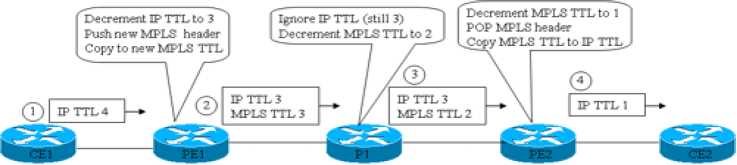
The term MPLS TTL propagation refers to the combined logic as shown in the figure. In effect, the MPLS routers propagate the same TTL value across the MPLS network-the same TTL values that would have occurred if MPLS was not used at all. As you might expect, a truly looping packet would eventually decrement to TTL 0 and be discarded. Additionally, a traceroute command would receive ICMP Time Exceeded messages from each of the routers in the figure, including the LSRs.
However, many engineers do not want hosts outside the MPLS network to have visibility into the MPLS network with the traceroute command. SPs typically implement MPLS networks to create Layer 3 WAN services, and the SP's customers sit outside the MPLS network. If the SP's customers can find the IP addresses of the MPLS LSRs, it may annoy the customer who wants to see only customer routers, and it may create a security exposure for the SP.
Cisco routers can be configured to disable MPLS TTL propagation. When disabled, the ingress E-LSR sets the MPLS header's TTL field to 255, and the egress E-LSR leaves the original IP header's TTL field unchanged. As a result, the entire MPLS network appears to be a single router hop from a TTL perspective, and the routers inside the MPLS network are not seen from the customer's traceroute command.