9.2 Label Switched Path (LSP)
One of the most popular of the MPLS applications is the MPLS VPN. MPLS VPNs allow a service provider, or even a large enterprise, to offer Layer 3 VPN services. In particular, SPs oftentimes replace older Layer 2 WAN services such as Frame Relay and ATM with an MPLS VPN service. MPLS VPN services enable the possibility for the SP to provide a wide variety of additional services to its customers because MPLS VPNs are aware of the Layer 3 addresses at the customer locations. Additionally, MPLS VPNS can still provide the privacy inherent in Layer 2 WAN services.
MPLS VPNs use MPLS unicast IP forwarding inside the SP's network, with additional MPLS-aware features at the edge between the provider and the customer. Additionally, MPLS VPNs use MP-BGP to overcome some of the challenges when connecting an IP network to a large number of customer IP internetworks-problems that include the issue of dealing with duplicate IP address spaces with many customers.
9.2.1 MPLS VPNs
The protocols and standards defined by MPLS VPNs solve the problems shown in our example and provide a much larger set of features. In particular, the MPLS VPN RFCs define the concept of using multiple routing tables, called Virtual Routing and Forwarding (VRF) tables, which separate customer routes to avoid the duplicate address range issue. This section defines some key terminology and introduces the basics of MPLS VPN mechanics.
MPLS uses three terms to describe the role of a router when building MPLS VPNs. Note that the names used for the routers in most of the figures in this section have followed the convention of identifying the type of router as CE, PE, or P, as listed here.
Customer edge (CE)- A router that has no knowledge of MPLS protocols and does not send any labeled packets but is directly connected to an LSR (PE) in the MPLS VPN.
Provider edge (PE)- An LSR that shares a link with at least one CE router, thereby providing function particular to the edge of the MPLS VPN, including IBGP and VRF tables
Provider (P)- An LSR that does not have a direct link to a CE router, which allows the router to just forward labeled packets, and allows the LSR to ignore customer VPNs' routes
The key to understanding the general idea of how MPLS VPNs work is to focus on the control plane distinctions between PE routers and P routers. Both P and PE routers run LDP and an IGP to support unicast IP routing. However, the IGP advertises routes only for subnets inside the MPLS network, with no customer routes included. As a result, the P and PE routers can together label switch packets from the ingress PE to the egress PE.
9.2.1.1 The MPLS VPN Control Plane
The MPLS VPN control plane defines protocols and mechanisms to overcome the problems created by overlapping customer IP address spaces, while adding mechanisms to add more functionality to an MPLS VPN, particularly as compared to traditional Layer 2 WAN services. To understand the mechanics, you need a good understanding of BGP, IGPs, and several new concepts created by both MP-BGP RFCs and MPLS RFCs.
9.2.1.2Route Virtual Routing and Forwarding Tables
To support multiple customers, MPLS VPN standards include the concept of a virtual router. This feature, called a VRF table, can be used to store routes separately for different customer VPNs. The use of separate tables solves part of the problems of preventing one customer's packets from leaking into another customer's network due to overlapping prefixes, while allowing all sites in the same customer VPN to communicate. A VRF exists inside a single MPLS-aware router. Typically, routers need at least one VRF for each customer attached to that particular router.
Each VRF has three main components, as follows:
An IP routing table (RIB)
A CEF FIB, populated based on that VRF's RIB
A separate instance or process of the routing protocol used to exchange routes with the CEs that need to be supported by the VRF
For example, the example shown below shows more detail about router PE2, now with MPLS VPNs implemented. In this case, PE2 will use RIP-2 as the IGP to both customer A (router CE-A2) and customer B (router CE-B2). (The choice of routing protocol used from PE-CE is unimportant to the depth of explanations shown here.)
Adding Routes Learned from a CE to VRFs on Router PE2
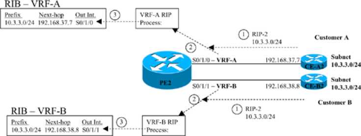
The figure shows three parallel steps that occur with each of the two customers. Note that step 1 for each customer does not occur at the same instant in time, nor does step 2, nor step 3; the figure lists these steps with the same numbers because the same function occurs at each step. The explanation of the steps is as follows:
1. The CE router, which has no knowledge of MPLS at all, advertises a route for 10.3.3.0/24 as normal-in this case with RIP-2.
2. In the top instance of step 2, the RIP-2 update arrives on PE2's S0/1/0, which has been assigned to customer A's VRF, VRF-A. PE2 uses a separate RIP process for each VRF, so PE2's VRF-A RIP process interprets the update. Similarly, the VRF-B RIP process analyzes the update received on S0/1/1 from CE-B2.
3. In the top instance of step 3, the VRF-A RIP process adds an entry for 10.3.3.0/24 to the RIB for VRF-A. Similarly, the bottom instance of step 3 shows the RIP process for VRF-B adding a route to prefix 10.3.3.0/24 to the VRF-B RIB.
9.2.2 Duplicate Customer Address Ranges
When an SP connects to a wide variety of customers using a Layer 2 WAN service such as Frame Relay or ATM, the SP does not care about the IP addressing and subnets used by those customers. However, in order to migrate those same customers to a Layer 3 WAN service, the SP must learn address ranges from the various customers and then advertise those routes into the SP's network. However, even if the SP wanted to know about all subnets from all its customers, many enterprises use the same address ranges (The reserved RFC 1918 address space, for example).
If you tried to support multiple customers using MPLS unicast IP routing alone, the routers would be confused by the overlapping prefixes, as shown in the figure below. In this case, the network shows five of the SP's routers inside a cloud. Three customers (A, B, and C) are shown, with two customer routers connected to the SP's network. All three customers use network 10.0.0.0, with the three customer sites on the right all using subnet 10.3.3.0/24.
The Main Challenge with Supporting Layer 3 VPNs
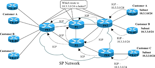
The first and most basic goal for a Layer 3 VPN service is to allow customer A sites to communicate with customer A sites-and only customer A sites. However, the network here fails to meet this goal for several reasons. Because of the overlapping address spaces, several routers would be faced with the dilemma of choosing one customer's route to 10.3.3.0/24 as the best route, and ignoring the route to 10.3.3.0/24 learned from another customer. For example, PE2 would learn about two different 10.3.3.0/24 prefixes. If PE2 chooses one of the two possible routes-for example, if PE2 picked the route to CE-A2 as best-then PE2 could not forward packets to customer B's 10.3.3.0/24 off router CE-B2. Also, a possibly worse effect is that hosts in one customer site may be able to send and receive packets with hosts in another customer's network. Following this same example, hosts in customer B and C sites could forward packets to subnet 10.3.3.0/24, and the routers might forward these packets to customer A's CE-A2 router.