5.1 Queuing
IOS makes use of a queue for packets on a router that are waiting to be transmitted when the output interface is occupied. A single queue using the first-out (FIFO) scheduling method is the simpler queuing method that has an impact on delay, jitter and packet dropping. In this scheduling method, IOS deploys the packet that arrived ahead of the other packets, in the queue, first. Since there is only one queue, no classification takes place. However, with FIFO scheduling, tail dropping can occur when the queue is full because the
queue itself has a limited, set size. Having a shorter queue would increase the possibility of tail dropping, while delay and jitter are decreased. Having a larger single queue would decrease tail dropping and packet loss, but it increases the delay factor, as well as jitter. When the single queue is long or short and congestion occurs over a period of time, packets would be dropped. This occurs simply because the amount of bytes attempting to leave the interface surpasses the speed of the interface. Packet size has no impact on queue length because the queues do not actually carry the packets. The queue carries pointers to the packets. The information contained by these pointers is kept in buffers.
| Tail Drop |
|---|
| Tail drop occurs when a router drops a packet when it wants to put the packet at the end or the tail of the queue but the queue is full. |
Because of these considerations, the FIFO queuing method should have a minimum of two queues. When two queues are used, the header of the packet is looked at, and the packet is then placed in a queue based on matching values within this header. The router initially first ascertains whether enough space is available in the queue, prior to placing the packet in the particular queue. When there is inadequate space, the packet is merely dropped. Once in the queue, the queuing scheduler determines which packet to transmit next. The queue scheduler can process one queue ahead of another, and can also withhold bandwidth for a favored queue. This procedure is known as the service algorithm of the queue. Packets are not reorganized once in the queue because the FIFO queuing method is used. Packets of a favored queue would therefore have less delay and jitter.
5.1.1 Transmit Queues (TX Queues) / Transmit Rings (TX Ring)
When packets leave the output queue on an interface, they are first placed into another FIFO queue on the interface before being sent. This queue is known as a Transmit Queue (TX Queue) or Transmit Ring (TX Ring). The actual terminology (TX Queue, TX Ring) is only related to the model of the router in use. The concepts and theories associated with both names are therefore the same. The purpose of this queue is to strengthen the use of the link, to basically full capacity (100 percent), as the packets pause to leave the interface. In this manner, the interface is not solely dependent on the general processor of the router for transmitting the packets. Packets can still be transmitted by the interface when the general processor is occupied, because the TX queue uses the Application Specific Integrated Circuits (ASICs) related to the interface.
Queuing tools do not establish and control interface TX Queues or TX Rings but the output queues. A single TX Queue is used on an interface. This queue is not influenced by any queuing configuration associated to the router. The TX Queue can however affect the processing of the queuing scheduling. When there is sufficient space in the TX Queue, no output queuing occurs because the packets are merely placed into the TX Queue. The packets therefore exit the interface in the order that they arrived. To minimize the impact of the TX Queue on the output queuing tools, the size of the TX Queue is automatically decreased to a low number by IOS when output queuing is enabled. The value is normally two, when output queuing tools are running on the interface. This value can however be changed. In this manner, the QoS queuing tools are not heavily impacted and there is still always a packet readily accessible for transmitting in the TX Queue.
5.1.2 Sub-interface and Virtual Circuit (VC) Queuing
Queuing can also occur on sub-interfaces and VCs when traffic shaping is functioning on the interface. These shaping queues are also managed by queuing tools in the same manner as QoS tools manage the output queue of the interface. Packets from traffic shaping queues move to the output queue, and then to the
TX Queue of the interface. However, traffic shaping can lead to full sub-interface queues because the movement of traffic exiting the interface is slowed down. Congestion can occur between the traffic shaping queue and the output queue of the interface because packets can only exit the traffic shaping queue at the traffic shaping contract rate. When a new packet is within the shaping contract rate, the packet is not delayed. In this instance, the packet is placed in the output queue or the TX Queue.
5.1.3 Priority Queuing (PQ)
With PQ, the queues with a higher priority are processed prior to the queues with the low priorities. PQ is best suited for QoS policies that have to provide the best service to one traffic type. The big drawback is that the lower priority queues tend to degrade swiftly. This therefore makes PQ unfeasible for the majority of applications around.
PQ has a maximum of four queues, called High, Medium, Normal and Low. The PQ scheduler first processes packets from the High queue, and when no packets are in the High queue; a packet is processed from the Medium queue. The High queue therefore always gets maximum bandwidth and packets in this queue experience little delay and jitter. After this packet is processed, the PQ scheduler begins its process by servicing the High queue again. The Normal queue is processed when there are no packets waiting to be serviced in the previous two queues, and the Low queue is only processed when there are no packets waiting in the previous three queues. The normal and low queues experience great delay when there is congestion on the link. In cases, user applications may be greatly impacted in a negative manner when packets are in these lower queues.
In each queue, FIFO logic is used. The PQ scheduler moves the packet from the highest priority queue to the TX Queue when the TX Queue has available space. With reference to the previous discussion on the TX Queue and the QoS tools, PQ will not function when the TX Queue is empty. When the TX Queue is empty, packets are placed straight in that queue. When the TX Queue fills, PQ is enabled again and PQ commences the queuing process. When the TX Queue empties again PQ ceases because the packets are again placed directly in the TX Queue.
With PQ, the packets are classified based on the packet header contents. This queuing method can directly match packets according to the incoming interface, TCP and UDP port numbers, and length of the packet. PQ can also match packets using ACLs for the majority of the Layer 3 protocols. Tail drop is the only drop policy. When the queue intended for the packet is full, the packet is dropped. The maximum queue length is infinite length. Packets are only no longer queued when the router is out of memory. This option is set with zero. The following are the default setting:
High Queue: 20 packets
Medium Queue: 40 packets
Normal Queue: 60 packets
High Queue: 80 packets
5.1.3.1 Configuring PQ
PQ configuration is similar to access-control list (ACL) configuration. The difference being that the objective is to queue a packet rather than discard it. Global commands are used to define the logic for classifying packets by matching header fields, and an interface subcommand is used to enable PQ on an interface.
The configuration commands for PQ are:
priority-list list-number protocol protocol- name {high| medium| normal| low} queue-keyword keyword-value: A global configuration command used to create a priority list entry, set classification first by protocol, and then further refine it with keywords. It also identifies the queue into which to place matched packets.
priority-list list_number interface interface_type interface_number {high | medium |
normal | low}: A global configuration command used to create a priority list entry, set classification based on the incoming interface, and then identify the queue into which to place matched packets.
priority-list list_number queue-limit [high_limit [medium_limit [normal_limit
[low_limit]]]]: A global configuration command used to set queue lengths for the 4 queues, respectively.
priority-list list_number default {high | medium | normal | low}: Used to change the default queue for packets that are not matched.
priority-group list_number: Interface subcommand; enables a priority list for packets exiting an interface.
The exec commands for PQ are:
show queue interface_name interface_number [vc [vpi/] vci]]: Lists information about the packets that are waiting in a queue on the interface.
show queuing [custom | fair | priority | random-detect [interface atm-subinterface
[vc [[vpi/] vci]]]]: Lists the configuration and statistical information about the queuing tool on an interface.
5.1.4 Custom Queuing (CQ)
CQ services all queues, even when congestion takes place. With CQ, 16 queues are used, which therefore facilitates 16 classification categories. CQ gives the queues numbers as names, like Queue 1, Queue 2 and so forth. The FIFO logic is used within every queue. However, CQ cannot provide exceptional service for delay and jitter sensitive traffic because its scheduler cannot always process one queue above another. CQ is therefore suited for networks that do not have jitter sensitive applications. As with PQ, tail drop is the only drop policy offered.
With CQ, the packets are classified based on the packet header contents. This queuing method can directly match packets according to the incoming interface, TCP and UDP port numbers, and length of the packet. CQ can also match packets using ACLs for the majority of the Layer 3 protocols. CQ therefore uses the same classification methods as PQ. In the same manner as with PQ, the maximum queue length can be set, which is infinite length. The default setting is 20 packets per queue.
The CQ scheduler provides each queue with an estimate percentage of total bandwidth. CQ round robins through the queues, and commences with the first queue. The first queue is serviced until the assigned byte count is reached, or the queue does not have any more packets. After this, CQ services the second queue, and then proceeds to process the different byte counts for every queue. CQ therefore processes the amount of bytes for each queue as it round robins through the queues.
5.1.4.1 Configuring CQ
CQ configuration is similar to PQ configuration. Global commands are used to define the logic for classifying packets by matching header fields, and an interface subcommand is used to enable CQ on an interface.
The configuration commands for CQ are:
queue-list list_number protocol protocol_name queue_number queue_keyword
keyword_vaiue: A global configuration command used to create a custom queue list entry, set classification first by protocol, and then further refine it with keywords. It also identifies the queue into which to place matched packets.
queue-list list_number interface interface_type interface_number queue_number: A
global configuration command used to create a custom queue list entry, set classification based on incoming interface, and then identify queue into which to place matched packets.
queue-list list_number queue cqueue_number byte-count byte_count_number: A global
configuration command used to set the byte count for the specified queue, i.e., the number of bytes taken from this queue each pass.
queue-list list_number queue queue_number limit limit_number: A global configuration command used to set queue lengths for the specified queue.
queue-list list_number default queue_number: Used to change the default queue for packets that are not matched.
custom-queue-list [list_number]: An interface subcommand which enables a custom queue list for packets exiting an interface.
The exec commands for CQ are:
show queue interface_name interface_number [vc [vpi/] vci]]: Lists information about the packets that are waiting in a queue on the interface.
show queueing [custom | fair | priority | random-detect [interface atm-subinterface
[vc [[vpi/] vci]]]]: Lists the configuration and statistical information about the queuing tool on an interface.
5.1.5 Weighted Fair Queuing (WFQ)
With WFQ, packets are classified in accordance with flows that are based on the following:
Source IP Address
Destination IP Address
TCP or UDP Source Port Number
TCP or UDP Destination Port Number
UDP or TCP transport layer protocol type within the IP header
Packets belong to the same flow when they have the same details defined above. The DSCP field should be set to the same value for packets that should be classified into an identical flow. A maximum of 4096 queues are allowed for each interface. The FIFO logic is used within every queue. There are no classification options available with WFQ. The WFQ scheduler treats the low volume high precedence flows better than the large volume low precedence flows.
WFQ only considers a flow to be active when packets from the flow are waiting to exit the interface. When no packets are queued for a particular flow, WFQ removes the flow. Therefore, when using WFQ, the number of queues can vary quite swiftly.
The WFQ scheduler has the following two important objectives:
The first objective is providing an equal amount of bandwidth to each flow exiting the interface based on the clock rate. This is similar to Time Division Multiplexing (TDM). A queue with a lower amount of packets will exit faster than a queue with a higher volume of packets. Queues with higher volumes tend to have more delay and jitter associated to it. The WFQ scheduler does permit these flows to utilize excess bandwidth from the lower volume queues.
The other objective is to enable greater bandwidth for flows having the higher IP precedence settings / values. WFQ gives an amount of bandwidth that is derived from the ratio of precedence of every flow, in addition to one.
Therefore WFQ is best suited for a network where the lower volume traffic is provided with the higher precedence values, and is actually the delay sensitive traffic. Voice and video traffic need low delay and jitter and WQF is therefore not suited for these traffic types as is has no priority queue.
With WFQ, the scheduler attempts to give each queue a weighted percentage of bandwidth. These bandwidth percentages vary quickly because the amount of flows differs swiftly. In addition to this, the percentage of link bandwidth for every queue changes as the precedence values changes. This makes it fairly impossible to use WFQ with a byte count or an allocated percentage of bandwidth for every queue.
WFQ works out the sequence number (SN) of the packet prior to it being placed into a queue. When there is space in the TX Queue, WFQ places a packet with the lowest SN between the queues, in the TX Queue. This SN forms part of the modified tail drop logic. The SN calculation is based on the length and precedence of the packet.
The SN of a packet is calculated as follows:
PreviousSN + weight * Length of the new packet
Length of the new packet: The SN calculation for the larger packets will have a higher number as an outcome. Small packets will have a lower number as an outcome.
PreviousSN: This component of the calculation will result in a larger number being allocated for packets, in those queues that currently have the larger number of packets already in that queue.
Weight: These values are assigned to the precedence values in a contrariwise manner. The higher precedence values receive a lower weight value. The weight values used by WFQ prior to release 12.0(5)T/12.1, and after release 12.0(5)T/12.1 are listed below:
Precedence 0: Before 4096, after 32384
Precedence 1: Before 2048, after 16192
Precedence 2: Before 1365 after 10794
Precedence 3: Before 1024, after 8096
Precedence 4: Before 819, after 6476
Precedence 5: Before 682, after 5397
Precedence 6: Before 585, after 4626
Precedence 7: Before 512, after 4048
A modified tail drop policy is used with WFQ. The policy considers various factors when deciding to tail drop a packet. A topmost packet limit is determined between all the queues, referred to as the hold queue limit. This limit is applicable to all the WFQ queues, and not just one queue. When this limit is exceeded, new packets are discarded. Another factor that is considered is a single queue's Congestive Discard Threshold (CDT). When a single queue's CDT is reached and a new packet needs to be located in that particular queue, the packet is discarded. The CDT can be set to a range from 1 - 4093. The SN is also considered in the tail drop policy. WFQ can drop a packet in a flow / queue when another separate flow /queue contain lower SNs, although it has surpassed the CDT.
5.1.5.1 Configuring WFQ
WFQ is the default setting on serial interfaces. The bandwidth setting is at T1/E1 speed and beneath. The commands associated with configuring WFQ are listed below:
fair-queue [congestive-discard-threshold [dynamic-queues[reservable-queues]]]: This command is used in interface configuration mode. The command defines the CDT, the maximum queue value, and the value for RSVP. The command also enables WFQ.
hold-queue length {in | out}: This interface configuration command should be used when wanting to modify the hold queue length.
show queueing [custom | fair | priority | random-detect [interface atm-subinterface [vc [[vpi/] vci]]]]: This command displays information about the queuing tool running on the interface. This command list information like the CDT and number of queues.
show queue interface-name interface-number [vc [vpi/] vci]] : This command displays information on packets that are queued on the interface.
5.1.5.2 Class Based WFQ (CBWFQ)
With CBWFQ it is possible to reserve bandwidth for every queue. The actual percentage of traffic can be configured instead of the byte count. One queue of CBWFQ can be used for WFQ. Packets are classified with the same fields used for CB marking. It therefore also includes NBAR, MPLS Experimental, source and destination MAC Addresses, the incoming interface, CoS, precedence, RTP port numbers and QoS Group. Basically, it can classify according to anything that the Modular QoS CLI (MQC) commands are capable of matching. CBWFQ uses the same configuration commands used for CB marking.
CBWFQ can have up to 64 queues, with a maximum default queue length of 64. A queue called the Class Default Queue is configured. When classification values that are configured do not happen to match a packet, the packet is placed in this queue. The FIFO logic is used within each queue, Queue 1 - Queue 63. The FIFO logic or WFQ can be used for the Class Default Queue (Queue 64). When WFQ is used for the
Class Default Queue, the packet with the favorable Sequence Number (SN) is elected. Recall that WFQ favors high precedence, and the low volume traffic, or interactive flows. CBWFQ therefore makes it possible to reserve bandwidth for certain packets, and the remainder of bandwidth can be allocated using WFQ.
The CBWFQ scheduler's end result is a definite percentage of bandwidth for each queue. Bandwidth is shared between the remainder of the queues when a queue(s) do not require their bandwidth percentages for a brief duration of time.
CBWFQ has a choice between two drop policies, namely tail drop and Weighted Random Early Detection (WRED). These drop policies are configurable on each queue. WRED drops packets prior to the queue becoming full with the end objective of decreasing the TCP connections, and congestion. WRED can be operating on all 64 queues but a factor to bear in mind is that WRED is not suited for voice and video traffic. In addition, dropping voice packets will degrade the quality of the voice. WRED is suited for data traffic.
CBWFQ uses the exact same commands used for configuring CB Marking. The additional class subcommands that CBWFQ uses with these commands are listed below:
bandwidth {bandwidth-kbps | percent percent}: This command is used for specifying the actual bandwidth or percentage bandwidth for the classes within a policy map.
fair-queue [queue-limit queue-value]: This command is used to enable WFQ on the Class Default Queue.
random-detect dscp dscpvalue min-threshold maxthreshold [mark-probability-denominator]: This command enables DSCP WRED
random-detect precedence precedence min-threshold maxthreshold mark-prob-denominator: This command enables precedence WRED The following interface subcommand is used with CBWFQ:
max-reserved-bandwidth percent: This command is used to set the link bandwidth percentage for all the queues, other than the Class Default Queue.
5.1.5.2.1 Low Latency Queuing (LLQ)
LLQ is a feature of CBWFQ that could be used on a single class. This class is then serviced as a priority queue. The LLQ scheduler always checks the Low Latency Queue first, and when packets are in this queue, they are serviced first. LLQ is therefore the best queuing QoS tool for delay and jitter sensitive traffic. LLQ stops traffic in the latency queue from using more than the set amount of bandwidth by dropping traffic once the limit is reached. The utilization of CAC and engineering would be possible preventative measures against traffic being dropped in the latency queue. When there are no packets in the latency queue, the other queues are serviced with guaranteed bandwidth for the traffic in those queues.
LLQ configuration uses an additional priority command with the CBWFQ commands. The priority command replaces the bandwidth command on the class. The following class subcommand is the priority command used for LLQ:
priority { bandwidth-kbps | percent percentage} [burst]: This command enables LLQ, the policing feature, and reserves the guaranteed bandwidth
5.1.5.2.2 IP RTP Priority
This is one of the older queuing tools. Cisco favors the use of LLQ over IP RTP Priority. With IP RTP Priority, a Priority Queue that is always processed first is added to CBWFQ or WFQ. A set amount of bandwidth is reserved. The Priority Queue is also policed to ensure that the set amount of bandwidth is not surpassed. IP RTP Priority can only classify even UDP port numbers. Only the VoIP payload is then chosen.
The following command, used in interface configuration mode is used to enable IP RTP Priority on an interface or sub interface:
ip rtp priority starting-rtp-port-number port-number-range bandwidth
The following command is used to enable IP RTP Priority in a Frame Relay Traffic Shaping (FRTS) map class that is subsequently enabled on a Data Link Connection Identifier (DLCI) or sub-interface:
frame-relay ip rtp priority starting-rtp-port-number port-number-range bandwidth
5.1.5.3 Distributed Weighted Fair Queuing (dWFQ)
WFQ Options for the Cisco 7500 Series
The 7500 architecture includes distributed processing on line cards called Versatile Interface Processors (VIPs). Many functions that the general-purpose processor on the Route Switch Processor (RSP) card would normally perform by can instead be distributed to the processor on the VIPs. This can be helpful in typical 7500 series configurations that use a large number of line cards and interfaces, relieving processing burden from the general-purpose RSP processor.
The Cisco IOS provides three streamlined WFQ options specifically designed for the Cisco 7500 series: flow-based dWFQ, ToS-based dWFQ, and QoS group-based dWFQ. All three tools require distributed CEF (dCEF) processing to be enabled globally, and on the interface on which distributed WFQ is enabled.
5.1.5.3.1 Flow-Based dWFQ
Flow-based dWFQ classifies packets based on the flow, examining the source and destination IP address and port and the protocol type. All of the other main features of dWFQ differ slightly when compared to WFQ.
Unlike WFQ, dWFQ does not queue a packet, only to discard it later because its sequence number (SN) is larger than a new packet's SN. Instead, dWFQ uses the terms "aggregate limit" and "individual limit" to determine the limit over all queues and the limit per queue, respectively. If the aggregate packet limit has been exceeded or the individual queue limit been exceeded, dWFQ drops the new packet. In so doing, dWFQ ignores the IP precedence value of a packet and does not weight the packet, totally ignoring the contents of the ToS byte.
In addition, dWFQ does allow for the maximum queue length to be changed, but the number of queues remains 512.
Another difference between WFQ and dWFQ is that dWFQ uses a mechanism called a calendar queue to sort all the packets waiting in a dWFQ queue whereas WFQ uses a simple sorted linked list. The effect, however, is the same-both schedulers select the packet with the lowest SN as the next packet to be forwarded to the TX Queue/TX Ring. However, by using a calendar queue, dWFQ performs the final scheduling function more efficiently, which is particularly useful on higher-speed interfaces.
Like WFQ, flow-based dWFQ configuration requires little effort. The fair-queue interface subcommand enables flow-based dWFQ on the interface. You can use the fair-queue aggregate-limit and fair-queue individual-limit commands to change the aggregate or individual queue limits, respectively. You can also use the same show commands to examine the status of dWFQ.
The configuration commands for flow-based dWFQ are:
fair-queue: An interface configuration mode command which enables dWFQ on the interface. There are no other parameters on this command when it is used with dWFQ.
fair-queue aggregate-limit aggregate_packets: An interface configuration mode command used to set the aggregate limit of the number of packets held in all dWFQ queues.
fair-queue individual-limit individual_packet: An interface configuration subcommand used to set the maximum number of packets in a single queue.
The exec commands for flow-based dWFQ are:
show queue interface-name interface-number [vc [vpi/] vci]] : Displays information on packets that are queued on the interface.
show queueing [custom | fair | priority | random-detect [interface atm-subinterface [vc [[vpi/] vci]]]]: Displays information about the queuing tool running on the interface. This command list information like the CDT and number of queues.
5.1.5.3.2 TOS-Based dWFQ
When compared with WFQ, ToS-Based dWFQ uses a completely different classification method and scheduler. ToS-Based WFQ classification is based on values of the second and third bits (the two low-order bits) in the IP Precedence field. It places packets into one of four queues based on these values and does not consider the flow at all. In other words, it is a class-based tool, not a flow-based tool. ToS-Based dWFQ use a fair-queuing scheduler, with the weighting based on the configured bandwidth percentages.
The ToS-Based WFQ classification function cannot be changed. Thus, precedence 0 and 4 go into Queue 0, because decimal 0 converts to 000, and decimal 4 converts to 100, therefore the two low-order bits are equal (00). Likewise, precedence 1 and 5 go into Queue 1 (decimal 1 converts to 001, and decimal 5 converts to 101), precedence 2 and 6 go into Queue 2 (decimal 2 converts to 010, and decimal 6 converts to 110), and precedence 3 and 7 go into Queue 3 (decimal 3 converts to 011, and decimal 7 converts to 111).
The drop policy is the same as flow-based dWFQ, using an aggregate limit and individual queue limit method to set the value.
The scheduler provides a percentage of bandwidth for each queue. The scheduler logic works like WFQ, using SNs. IOS derives the weights for each queue based on the configured bandwidth percentages. The percentages default to 10 percent, 20 percent, 30 percent, and 40 percent, for Queues 0 through 3, respectively. You can configure the percentages for Queues 1 through 3, with the rest being assigned to Queue 0.
Like WFQ, TOS-based dWFQ configuration requires little effort. You enable ToS-Based dWFQ on an interface by configuring the fair-queue tos subcommand on that interface. However, for this command to work, distributed CEF (dCEF) must be enabled, and the interface must really be on a VIP2-40 or higher.
The configuration commands for TOS-based dWFQ are:
fair-queue tos: An interface configuration mode command which enables TOS-based dWFQ on the interface. There are no other parameters on this command when it is used with dWFQ.
fair-queue aggregate-limit aggregate_packets: An interface configuration mode command used to set the aggregate limit of the number of packets held in all dWFQ queues.
fair-queue individual-limit individual_packet: An interface configuration subcommand used to set the maximum number of packets in a single queue.
fair-queue {qos-group number | tos number} limit class_packet: An interface configuration subcommand used to set the individual queue limit for a single queue. This command takes precedence over the fair-queue individual-limit command.
fair-queue {qos-group number | tos number} weight weight: An interface configuration subcommand used to set the percentage link bandwidth assigned to the queue. The tos parameter can be set to 1, 2, or 3.
The exec commands for TOS-based dWFQ are:
show queue interface-name interface-number [vc [vpi/] vci]] : Displays information on packets that are queued on the interface.
show queueing [custom | fair | priority | random-detect [interface atm-subinterface [vc [[vpi/] vci]]]]: Displays information about the queuing tool running on the interface. This command list information like the CDT and number of queues.
5.1.5.3.3 Distributed QoS Group-Based WFQ
QoS Group-Based dWFQ is similar to ToS-Based WFQ. The classification feature of each is similar, but with QoS Group-Based dWFQ, the classification is based on the QoS group value assigned to the packet. The QoS group is a value between 0 and 99, inclusive, which is assigned to the packet as it passes through a single router. QoS Group-Based dWFQ classifies a packet into 1 of 100 queues, numbered 0 through 99, matching the QOS group assigned to the packet with Queue 0 being the default queue.
The drop policy and scheduler also the same as ToS-Based dWFQ, though the bandwidth percentages can be spread among as many as 100 queues.
Again, the configuration for QoS Group-Based dWFQ is simple. The configuration commands for QoS Group-Based dWFQ are:
fair-queue qos-group: An interface configuration mode command which enables QoS Group-Based dWFQ on the interface. There are no other parameters on this command when it is used with dWFQ.
fair-queue aggregate-limit aggregate_packets: An interface configuration mode command used to set the aggregate limit of the number of packets held in all dWFQ queues.
fair-queue individual-limit individual_packet: An interface configuration subcommand used to set the maximum number of packets in a single queue.
fair-queue {qos-group number | tos number} limit class_packet: An interface configuration subcommand used to set the individual queue limit for a single queue. This command takes precedence over the fair-queue individual-limit command.
fair-queue {qos-group number | tos number} weight weight: An interface configuration subcommand used to set the percentage link bandwidth assigned to the queue. The qos-group number can be between 1 and 99, with Queue 0 getting the remaining bandwidth.
The exec commands for QoS Group-Based dWFQ are:
show queue interface-name interface-number [vc [vpi/] vci]] : Displays information on packets that are queued on the interface.
show queueing [custom | fair | priority | random-detect [interface atm-subinterface [vc [[vpi/] vci]]]]: Displays information about the queuing tool running on the interface. This command list information like the CDT and number of queues.
5.1.6 Modified Deficit Round-Robin (MDRR)
Modified Deficit Round-Robin (MDRR) was designed specifically for the Gigabit Switch Router (GSR) models of Internet routers as the other QoS queuing tools such as WFQ, CBWFQ, PQ, CQ, etc., are not supported on the GSRs.
Like all queuing tools, MDRR needs to perform classification and make drop decisions, scheduling decisions, and so forth. MDRR classifies packets only based on the IP Precedence field. Hence, MDRR supports eight classes, and therefore eight queues, because there are eight precedence values. The queues are numbered 0 through 7, and the precedence values (decimal) are also 0 through 7- but MDRR does map the values one to one; thus allowing you to configure each precedence value to map to any of the queues, so more than one precedence value could map to the same queue.
Like CBWFQ, MDRR supports either tail drop or Weighted Random Early Detection (WRED) for the drop policy, per queue. Inside each queue, first-in, first-out (FIFO) logic is used.
MDRR schedules traffic by making a round-robin pass through the configured queues. MDRR removes packets from a queue, until the quantum value (QV) for that queue has been removed. The QV quantifies a number of bytes, and is used much like the byte count is used by the CQ scheduler. MDRR repeats the process for every queue, in order from 0 through 7, and then repeats this round-robin process. The end result is that each queue gets some percentage bandwidth of the link.
MDRR also allows one queue to be used as a PQ, but with two differences on how the PQ is scheduled. One scheduling option, called strict scheduling, acts like PQ's treatment of the High queue, which is also how Low Latency Queuing (LLQ) and IP RTP Priority scheduling works. Whenever the scheduler decides to remove another packet from any queue, it first checks the strict PQ, and takes a packet if one is in the queue. With strict treatment, MDRR does not need to assign a QV to the low-latency queue, because there is no concept of taking a QV of bytes per pass through the queue. MDRR offers a less strict algorithm for servicing the low-latency queue called alternate service. With alternate service, the low-latency queue is assigned a QV, just like the other queues. MDRR takes QV bytes from the low-latency queue, and then take bytes from a non-low-latency queue. MDRR then goes back to the low-latency queue, taking QV bytes, and then to another queue.
Strict scheduling and alternate service affect delay and jitter differently. With alternate service, packets experience longer delay and more jitter, as compared with strict scheduling. Alternate service also gives the other queues a little more service which improves their performance.
5.1.6.1 Configuring MDRR
MDRR configuration requires that you understand a bit about GSR architecture and also introduces some new terminology. The following section discusses the MDRR configuration commands.
cos-queue-group cos_queue-group_name: A global configuration mode command used to create a queue group template, where other parameters are added as subcommands.
precedence <0-7> queue [ <0-6> | low latency]: A cos-queue subcommand which maps a precedence value to a queue.
queue queue_number weight: A cos-queue subcommand which assigns a weight to a queue.
queue low-latency{alternate-priority weight | strict-priority}: A cos-queue subcommand which enables a queue as a low-latency queue, defines scheduling strategy, and assigns weight.
random-detect-label label min_threshold max_threshold mark_probability: A cos-queue subcommand which creates a set of WRED parameters.
precedence queue_nvmber random-detect-label label: A cos-queue subcommand which enables WRED on the queue, with the WRED parameters in the random-detect-label specified.
5.1.7 Cisco Modular QoS CLI
For many years and over many IOS releases, Cisco added QoS features and functions, each of which used its own separate set of configuration and exec commands. Eventually, the number of different QoS tools and different QoS commands got so large that QoS configuration became a big chore. Cisco created the Modular QoS CLI (MQC) to help resolve these problems, by defining a common set of configuration commands to configure many QoS features in a router or switch.
MQC is not a totally new CLI, different from IOS configuration mode, for configuring QoS. Rather, it is a method of categorizing IOS classification, marking, and related actions into logical groupings to unify the command-line interface. MQC defines a new set of configuration commands-commands that are typed in using the same IOS CLI, in configuration mode. However, once you understand MQC, you typically need to learn only one new command to know how to configure any additional MQC-based QoS tools. You can identify MQC-based tools by the name of the tool; they all begin with the phrase "Class-Based" (abbreviated CB for this discussion). These tools include CB Marking, CB Weighted Fair Queuing (CBWFQ), CB Policing, CB Shaping, and CB Header Compression.
Mechanics of MQC
MQC separates the classification function of a QoS tool from the action (PHB) that the QoS tool wants to perform. To do so, there are three major commands with MQC, with several subordinate commands:
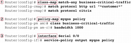
The class-map command defines the matching parameters for classifying packets into service classes.
The PHB actions (marking, queuing, and so on) are configured under a policy-map command.
The policy map is enabled on an interface by using a service-policy command.
A Sample Application of MQC
For each class, some QoS action (PHB) needs to be performed; this action is configured using the policy-map command. Under a single policy map, multiple classes can be referenced. Inside the single policy called mypolicy, under each of the two classes myclass1 and myclass2, you can configure separate QoS actions. For instance, you could apply different markings to packets in myclass1 and myclass2 at this point. Finally, when the service-policy command is applied to an interface, the QoS features are enabled either inbound or outbound on that interface.
5.1.7.1 Classification Using Class Maps
MQC-based tools classify packets using the match subcommand inside an MQC class map. The following list details the rules surrounding how class maps work for matching and classifying packets:
The match command has many options for matching packets, including QoS fields, ACLs, and MAC addresses.
Class-map names are case sensitive.
The match protocol command means that IOS uses Network Based Application Recognition (NBAR) to perform that match.
The match any command matches any packet-in other words, any and all packets.
The following example shows a simple CB Marking configuration, with comments focused on the classification configuration.
Basic CB Marking Example
! CEF is required for CB Marking. Without it, the class map and policy map ! configuration would be allowed, but the service-policy command would be rejected. ip cef
! The first class map matches all UDP/RTP packets with UDP ports between 16384 and ! 32767 (the 2nd number is added to the first to get the end of the range.) The ! second class map matches any and all packets. class-map match-all msclass!
match ip rtp 16384 16383 class-map match-all myclass2 match any
! The policy map calls each of the two class maps for matching. The set command ! implies that the PHB is marking, meaning that this is a CB Marking config. policy-map mypolicy class myclass1 set dscp EF class myclass2 set dscp default
! The policy map processes packets leaving interface fa0/0. interface Fastethernet0/0 service-policy output mypolicy
With this packet each packet leaving interface fa0/0 will match one of the two classes. Because the policy map uses a set dscp command in each class, and all packets happen to match either myclass1 or myclass2, each packet will leave the interface marked either with DSCP EF (decimal 46) or default (decimal 0). (If the matching logic was different and some packets match neither myclass1 nor myclass2, those packets would not be marked, and would retain their existing DSCP values.)
Using Multiple match Commands
In some cases, a class map may need to examine multiple items in a packet to decide whether the packet should be part of that class. Class maps can use multiple match commands, and even nest class maps inside other class maps, to achieve the desired combination of logic. The following list summarizes the key points regarding these more complex matching options:
Up to four (CoS and IPP) or eight (DSCP) values can be listed on a single match cos, match precedence, or match dscp command, respectively. If any of the values are found in the packet, the statement is matched.
If a class map has multiple match commands in it, the match-any or match-all (default) parameter on the class-map command defines whether a logical OR or a logical AND (default) is used between the match commands, respectively.
The match class name command refers to another class map by name, nesting the named class map's matching logic; the match class name command is considered to match if the referenced class-map also results in a match.
The example below shows several examples of this more complicated matching logic, with notations inside the example of what must be true for a class map to match a packet.
Complex Matching with Class Maps
! class-map example1 uses match-all logic (default), so this class map matches ! packets that are permitted by ACL 102, and that also have an IP precedence of 5. class-map match-all example1 match access-group 102 match precedence 5
! class-map example2 uses match-any logic, so this class map matches packets that ! are permitted by ACL 102, or have DSCP AF21, or both.
class-map match-any example2 match access-group 102 match dscp AF21
! class-map example3 matches no packets, due to a common mistake-the two match ! commands use a logical AND between them due to the default match-all argument, meaning ! that a single packet must have DSCP 0 and DSCP 1, which is impossible. class-map example4 ! shows how to correctly match either DSCP 0 or 1. class-map match-all example3 match dscp 0 match dscp 1
!
class-map match-any example4 match dscp 0 1
! class-map i-am-nesting refers to class-map i-am-nested through the match class ! i-am-nested command. The logic is explained after the example. class-map match-all i-am-nested match access-group 102 match precedence 5
!
class-map match-any i-am-nesting match class i-am-nested match cos 5
The trickiest part of this example is how the class maps can be nested, as shown at the end. class-map i-am-nesting uses OR logic between its two match commands, meaning "I will match if the CoS is 5, or if class-map i-am-nested matches the packet, or both." When combined with the match-all logic of the i-am-nested class map, the logic matches the following packets/frames:
Packets that are permitted by ACL 102, AND marked with precedence 5 or
frames with CoS 5
5.1.7.2 Classification Using NBAR
NBAR classifies packets that are normally difficult to classify. For instance, some applications use dynamic port numbers, so a statically configured match command, matching a particular UDP or TCP port number, simply could not classify the traffic. NBAR can look past the UDP and TCP header, and refer to the host name, URL, or MIME type in HTTP requests. (This deeper examination of the packet contents is sometimes called deep packet inspection.) NBAR can also look past the TCP and UDP headers to recognize application-specific information. For instance, NBAR allows recognition of different Citrix application types, and allows searching for a portion of a URL string.
NBAR itself can be used for a couple of different purposes. Independent of QoS features, NBAR can be configured to keep counters of traffic types and traffic volume for each type. For QoS, NBAR can be used by CB Marking to match difficult-to-match packets. Whenever the MQC match protocol command is used, IOS is using NBAR to match the packets.
Popular Fields Matchable by CB Marking Using NBAR
|
Field |
Comments |
|---|---|
|
RTP audio versus video |
RTP uses even-numbered UDP ports from 16,384 to 32,768. The odd-numbered port numbers are used by RTCP for call control traffic. NBAR allows matching the even-numbered ports only, for classification of voice payload into a different service class from that used for voice signaling. |
|
Citrix applications |
NBAR can recognize different types of published Citrix applications. |
|
Host name, URL string, MIME type |
NBAR can also match URL strings, including the host name and the MIME type, using regular expressions for matching logic. |
|
Peer-to-peer applications |
NBAR can find file-sharing applications like KaZaa, Morpheus, Grokster, and Gnutella. |