3.6 IP Services and Applications
3.6.1 Address Resolution Protocol (ARP)
RARP |
|
Reverse ARP (RARP) provides a method for workstations to dynamically learn their IP address when they only know their MAC address. RARP was replaced by the Bootstrap Protocol (BOOTP) and Dynamic Host Configuration Protocol (DHCP) as the primary means to dynamically learn a device IP address. There are two time-to-live (TTL) attributes that are used to ensure efficient delivery: the TTL counter and the TTL threshold. The TTL counter is decremented by one every time the packet hops a router. Once the TTL counter is reaches zero, the packet is discarded. The TTL threshold provides greater granularity and are applied to specified interfaces of multicast-enabled routers. The router compares the threshold value of the multicast packet with the value specified in the interface configuration. If the TTL value of the packet is greater than or equal to the TTL threshold configured for the interface, the packet will be forwarded through that interface. This allows network administrators to limit the distribution of multicast packets beyond their boundaries by setting high values for outbound external interfaces. The maximum value for the TTL threshold is 255. |
| Proxy ARP |
|
Proxy ARP, as described in, specifies a method for which routers can respond to ARP requests from hosts that do not have a configured gateway, by replying with its local MAC address for destinations on other subnetworks. Cisco routers can reply to ARP requests for destination hosts on different major networks. Also, if the IP prefix is in the routing table, Cisco routers can send the ARP reply even if multiple segments are between the destination host and the router. Proxy ARP can be disabled per interface by using the interface configuration command no ip proxy-arp. |
When an IP packet needs to be sent over an Ethernet network, the 48-bit MAC physical address of the destination device needs to be determined. When given the destination IP address, ARP obtains the destination MAC. The destination MAC can be a local host or the gateway router's MAC address if the destination IP is across the routed network. The local host maintains an ARP table with a list of IP addresses to MAC addresses.
ARP operates by having the sender broadcast an ARP Request to all hosts in a segment. The ARP request contains the sender's IP address and MAC address; it also contains the target IP address. All nodes in the broadcast domain receive and process the ARP request. The device with the target IP address sends an ARP reply back to the sender with its MAC address information; the ARP reply is a unicast message. The sender now has the target MAC address in its ARP and can send the frame out.
Note: The specification for ARP is defined in RFC 826 while the specification for RARP is defined in RFC 903 and Proxy ARP is defined in RFC 1027.
3.6.2 BOOTP
BOOTP was first defined in RFC 951 and has been updated by RFC 1395, RFC 1497, RFC 1532, and RFC 1542. BOOTP is a protocol that allows a booting host to configure itself by dynamically obtaining its IP address, IP gateway, and other information from a remote server. This allows you to use a single server to centrally manage numerous network hosts without having to configure each host independently.
BOOTP is an application layer-based protocol that uses UDP/IP protocols for transport. UDP port 67 sends BOOTP requests to the BOOTP server, and the server uses UDP port 68 to send messages to the UDP client. The destination IP of the BOOTP requests uses the all-hosts (255.255.255.255), which are not forwarded by the router. If the BOOTP server is one or more router hops from the subnet, the local default gateway router must be configured to forward the BOOTP requests.
The interface command ip helper-address x.x.x.x is configured on interfaces with workstations that acquire their IP address information using BOOTP. The ip helper-address command changes the destination IP address of the BOOTP request and forwards it to the configured IP address. When an IP helper address is configured, UDP forwarding is enabled on default ports. The default ports are listed below.
Default BOOTP ports
|
Service |
Port |
|
TFTP |
UDP 69 |
|
DNS |
UDP 53 |
|
Time Service |
UDP 37 |
|
NetBIOS Name Server |
UDP 137 |
|
NetBIOS Datagram server |
UDP 138 |
|
BOOTP Server and Client |
UDP 67 and UDP 68 |
|
TACACS Service |
UDP 49 |
|
IEN-116 Name Service |
UDP 42 |
To prevent and control the forwarding of other protocols, you use the no ip forward-protocol udp [port] command. This is a global command and is not configured on an interface. For example, to forward TFTP, BOOTP, Terminal Access Controller Access Control System (TACACS), and a DNS broadcast, and prevent the other default protocols.
3.6.3 DHCP
Dynamic Host Configuration Protocol (DHCP) is defined in RFC 1531 and is based on BOOTP to provide a method to dynamically configure hosts on the network. DHCP adds the capability of reusing network addresses and additional configuration options. DHCP server hosts allocate network addresses and deliver configuration parameters dynamically to hosts. With DHCP, the computer can dynamically obtain its configuration information, such as IP address, subnet mask, IP default-gateway, DNS servers, Windows
Internet Naming Service (WINS) servers, etc. This configuration information is managed centrally on a DHCP server.
DHCP uses BOOTP relay agents (routers) to forward the DHCP requests to the server. Because DHCP is an extension of BOOTP, it uses the message format as defined in RFC 951 for BOOTP. It uses the same ports as BOOTP: DHCP messages to a server use UDP port 67, and DHCP messages sent to a client use UDP port 68. Because of this, the configuration to support DHCP in the routers is the same as described for BOOTP.
3.6.4 Hot Standby Routing Protocol (HSRP)
Hot Standby Routing Protocol (HSRP) is a Cisco protocol that provides automatic router backup. HSRP allows one router to assume the function of a second router if the second router fails. HSRP is useful for critical networks that need a failover router for network reachability. HSRP uses a priority scheme to determine the default active router. The default priority is 100. If you configure a router with a higher priority, it becomes the active router if both routers are configured at the same time. If a second (or third) router is configured after an HSRP router is already active, and that new router is configured with a higher priority, it does not take over the active role unless it's configured with the preempt command. A standards-based protocol similar to HSRP called Virtual Router Redundancy Protocol (VRRP) is defined in the proposed RFC 2338.
Although each router has its own physical MAC address and logical IP address, with HSRP they share a virtual MAC address and IP address. The active router assumes the virtual IP (VIP). The default gateway of hosts is configured with the VIP address. After a failure, the standby router takes over the active role. HSRP can also be configured to track an outgoing interface (usually a serial interface); if the interface fails, the active router resigns, and the standby router becomes the active router.
3.6.5 Internet Control Message Protocol (ICMP)
ICMP is a TCP/IP protocol designed to help manage and control the operation of a TCP/IP network. The ICMP protocol provides a wide variety of information about a network's status and is considered part of TCP/IP's network layer. ICMP can provide useful information for troubleshooting TCP/IP.
ICMP uses messages to accomplish its tasks. Many of these messages are used in even the smallest IP network.
ICMP Messages
| Message | Description |
|---|---|
| Destination Unreachable | Informs the source host that there is a problem delivering a packet. |
| Time Exceeded | Indicates that the time that it takes a packet to be delivered has expired and that the packet has been discarded. |
| Redirect | Indicates that the packet has been redirected to another router that has a better route to the destination address. The message informs the sender to use the better route. |
| Echo | Used by the ping command to verify connectivity. |
3.6.6 FTP and TFTP
File Transfer Protocol (FTP) and Trivial File Transfer Protocol (TFTP) are two popular file transfer protocols used in TCP/IP networks. Most end users use FTP, but Cisco router and switch administrators often use TFTP. FTP is a TCP-based application that has many options and features, including the capability to change directories, list files using wildcard characters, transfer multiple files with a single command, and use a variety of character sets or file formats. When a user, called a FTP client, attempts to connect to an FTP server, a TCP connection is established to the FTP server's well-known port 21. The user is required to enter a username and password, which the server uses to authenticate the files available to that user for read and write permissions. This security is based on the file security on the server's platform. All the commands used to control the transfer of a file are sent across this connection. At this point, the user has a variety of commands available to enable settings for transfer, change directories, list files, etc. However, whenever a get (mget for multiple files) or put (or mput for multiple files) command is entered, or the equivalent button is clicked on the user interface, a file is transferred. The data is transferred over a separate FTP data connection, another TCP connection, established to well-known port 20. This prevents a file transfer from impacting on the control connection.
Trivial File Transfer Protocol (TFTP) is a more basic file transfer protocol that use a small set of features, takes little memory to load, and little time to program. TFTP uses User Datagram Protocol (UDP), so there is no connection establishment and no error recovery by the transport layer. However, TFTP uses application layer recovery by embedding a small header between the UDP header and the data. This header includes codes along with a numbering scheme that numbers 512-byte blocks of data. The TFTP application uses these block numbers to acknowledge receipt and resend the data. TFTP sends one block and waits on an acknowledgment before sending another block.
3.6.7 DNS
Domain Name Service (DNS) is a method to manage Internet names in a distributed fashion. DNS servers return the destination IP addresses given the domain name. DNS was first specified by RFCs 882 and 883. The current specifications are RFCs 1034 and 1035.
DNS is a distributed database, where separate organizations administer domain name space and can then break the domain into several subdomains. DNS follows a reversed-tree structure for domain name space. The Internet Name Registration Authority manages the root of the tree.
DNS uses TCP and UDP port 53. UDP is the recommended transport protocol for DNS queries. TCP is the recommended protocol for zone transfers between DNS servers. A DNS query searches for the IP address of a Fully Qualified Domain Name (FQDN), such as www.testking.com.
3.6.8 SNMP
Simple Network Management Protocol (SNMP) is a network protocol for the management of network devices. SNMP allows network managers to inspect or change parameters on a device remotely. SNMP was first defined in RFC 1067 and was undated in RFCs 1155, 1157, and 1212. Version 2 of SNMP is defined in RFC 1442, with other RFCs providing updates. Version 3 of SNMP is described in RFC 2573.
In SNMP, managed devices contain an SNMP agent. The agents collect and store management information. The information is made available to the network management system (NMS). NMS uses read and write commands to query or change information on the SNMP agent. These commands use UDP port 161. Some devices can be configured to send a message to the NMS in the case of an interface failure or other defined event. The message sent to the server is a SNMP trap, which uses UDP port 162.
3.6.9 Network Time Protocol (NTP)
NTP Version 3 (RFC 1305) allows IP hosts to synchronize their time-of-day clocks with a common source clock. For instance, routers and switches can synchronize their clocks to make event correlation from an SNMP management station more meaningful, by ensuring that any events and traps have accurate time stamps.
By design, most routers and switches use NTP client mode, adjusting their clocks based on the time as known by an NTP server. NTP defines the messages that flow between client and server, and the algorithms a client uses to adjust its clock. Routers and switches can also be configured as NTP servers, as well as using NTP symmetric active mode�"a mode in which the router or switch mutually synchronizes with another NTP host.
NTP servers may reference other NTP servers to obtain a more accurate clock source as defined by the stratum level of the ultimate source clock. For instance, atomic clocks and Global Positioning System (GPS) satellite transmissions provide a source of stratum 1 (lowest/best possible stratum level). For an enterprise network, the routers and switches can refer to a low-stratum NTP source on the Internet, or purpose-built rack-mounted NTP servers, with built-in GPS capabilities, can be deployed.
3.6.10 Web Cache Communication Protocol (WCCP)
To ease pressure on congested WAN links in networks with many hosts, Cisco developed WCCP to coordinate the work of edge routers and content engines (also known as cache engines). Content engines collect frequently accessed data, usually HTTP traffic, locally, so that when hosts access the same pages the content can be delivered from the cache engine rather than crossing the WAN. WCCP differs from web proxy operation in that the hosts accessing the content have no knowledge that the content engine is involved in a given transaction.
WCCP works by allowing edge routers to communicate with content engines to make each aware of the other's presence and to permit the router to redirect traffic to the content engine as appropriate.
WCCP Operations Between a Router and a Content Engine
|
Step |
1. |
|
Step |
2. |
|
Step |
3. |
|
Step |
4A. |
|
Step |
4B. |
|
Step |
5. |
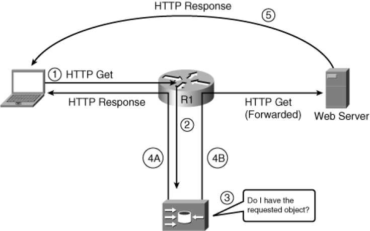
The figure shows the following steps, with the main decision point on the content engine coming at Step 4: The client sends an HTTP Get request with a destination address of the web server, as normal. The router's WCCP function notices the HTTP Get request and redirects the packet to the content engine.
The content engine looks at its disk storage cache to discover if the requested object is cached.
back to the client.
If the object is not cached, the content engine sends the original HTTP Get request on to the original server.
If Step 4B was taken, the server replies to the client, with no knowledge that the packet was ever redirected to a content engine.
Using WCCP, which uses UDP port 2048, a router and a content engine, or a pool of content engines (known as a cluster), become aware of each other. In a cluster of content engines, the content engines also communicate with each other using WCCP. Up to 32 content engines can communicate with a single router using WCCPv1. If more than one content engine is present, the one with the lowest IP address is elected as the lead engine.
WCCP also provides a means for content engines within a cluster to become aware of each other. Content engines request information on the cluster members from the WCCP router, which replies with a list. This permits the lead content engine to determine how traffic should be distributed to the cluster.
In WCCPv1, only one router can redirect traffic to a content engine or a cluster of content engines. In WCCPv2, multiple routers and multiple content engines can be configured as a WCCP service group. This expansion permits much better scalability in content caching. Furthermore, WCCPv1 supports only HTTP traffic (TCP port 80, specifically). WCCPv2 supports several other traffic types and has other benefits compared to WCCPv1:
- Supports TCP and UDP traffic other than TCP port 80, including FTP caching, FTP proxy handling, web caching for ports other than 80, Real Audio, video, and telephony.
- Permits segmenting caching services provided by a caching cluster to a particular protocol or protocols, and uses a priority system for deciding which cluster to use for a particular cached protocol.
- Supports multicast to simplify configuration.
- Supports multiple routers (up to 32 per cluster) for redundancy and load distribution. (All content engines in a cluster must be configured to communicate with all routers in that cluster.)
- Provides for MD5 security in WCCP communication using the global configuration command ip wccp password password.
- Provides load distribution.
- Supports transparent error handling.
When you enable WCCP globally on a router, the default version used is WCCPv2. Because the WCCP version is configured globally for a router, the version number affects all interfaces. However, multiple services can run on a router at the same time. Routers and content engines can also simultaneously participate in more than one service group. These WCCP settings are configured on a per-interface basis. Configuring WCCP on a router is not difficult because a lot of the configuration in a caching scenario takes place on the content engines; the routers need only minimal configuration.
WCCP Configuration Example
! First we enable WCCP globally on the router,
! specifying a service (web caching), a multicast address for ! the WCCP communication, and an MD5 password: ip wccp web-cache group-address 239.128.1.100 password cisco ! Next we configure an interface to redirect WCCP web-cache ! traffic outbound to a content engine: int fa0/0
ip wccp web-cache redirect out
! Finally, inbound traffic on interface fa0/1 is excluded from redirection: int fa0/1
ip wccp redirect exclude in
Finally, WCCP can make use of access lists to filter traffic only for certain clients (or to exclude WCCP use for certain clients) using the ip wccp web-cache redirect-list access-list global command. WCCP can also use ACLs to determine which types of redirected traffic the router should accept from content engines, using the global command ip wccp web-cache group-list access-list.
3.6.11 Network Address Translation (NAT)
Cisco Terminology |
|---|
Cisco uses the term inside local for the private IP addresses and inside global for the public IP addresses. The enterprise network that uses private addresses, and therefore that needs NAT, is the "inside" part of the network. The Internet side of the NAT function is the "outside" part of the network. A host that needs NAT has the IP address it uses inside the network, and it needs an IP address to represent it in the outside network. |
The advantage of using private IP addresses is that it allows an organization to use private addressing in a network, and use the Internet at the same time, by implementing Network Address Translation (NAT).
NAT is defined in RFC 1631 and allows a host that does not have a valid registered IP address to communicate with other hosts through the Internet. Essentially, NAT allows hosts that use private addresses or addresses assigned to another organization, i.e. addresses that are not Internet-ready, to continue to be used and still allows communication with hosts across the Internet.
NAT accomplishes this by using a valid registered IP address to represent the private address to the rest of the Internet. The NAT function changes the private IP addresses to publicly registered IP addresses inside each IP packet that is transmitted to a host on the Internet.
The Cisco IOS software supports several variations of NAT. These include Static NAT; Dynamic NAT; and Overloading NAT with Port Address Translation (PAT).
3.6.11.1 Static NAT
In Static NAT, the IP addresses are statically mapped to each other. Thus, the NAT router simply configures a one-to-one mapping between the private address and the registered address that is used on its behalf. Supporting two IP hosts in the private network requires a second static one-to-one mapping using a second IP address in the public address range, depending on the number of addresses supported by the registered IP address.
3.6.11.2 Dynamic NAT
Dynamic NAT is similar to static NAT in that the NAT router creates a one-to-one mapping between an inside local and inside global address and changes the IP addresses in packets as they exit and enter the inside network. However, the mapping of an inside local address to an inside global address happens dynamically. Dynamic NAT accomplishes this by setting up a pool of possible inside global addresses and defining criteria for the set of inside local IP addresses whose traffic should be translated with NAT.
With dynamic NAT, you can configure the NAT router with more IP addresses in the inside local address list than in the inside global address pool. When the number of registered public IP addresses is defined in the inside global address pool, the router allocates addresses from the pool until all are allocated. If a new packet arrives, and it needs a NAT entry, but all the pooled IP addresses are already allocated, the router discards the packet. The user must try again until a NAT entry times out, at which point the NAT function works for the next host that sends a packet. This can be overcome through the use of Port Address Translation (PAT).
3.6.11.3 Overloading NAT with Port Address Translation (PAT)
In some networks, most, if not all, IP hosts need to reach the Internet. If that network uses private IP addresses, the NAT router needs a very large set of registered IP addresses. If you use static NAT, each private IP host that needs Internet access needs a publicly registered IP address. Dynamic NAT lessens the problem, but if a large percentage of the IP hosts in the network need Internet access throughout normal business hours, a large number of registered IP addresses would also be required. These problems can be overcome through overloading with port address translation. Overloading allows NAT to scale to support many clients with only a few public IP addresses.
To support lots of inside local IP addresses with only a few inside global, publicly registered IP addresses, NAT overload uses Port Address Translation (PAT), translating the IP address as well as translating the port number. When NAT creates the dynamic mapping, it selects not only an inside global IP address but also a unique port number to use with that address. The NAT router keeps a NAT table entry for every unique combination of inside local IP address and port, with translation to the inside global address and a unique port number associated with the inside global address. And because the port number field has 16 bits, NAT overload can use more than 65,000 port numbers, allowing it to scale well without needing many registered IP addresses.
3.6.11.4 Translating Overlapping Addresses
NAT can also be used in organizations that do not use private addressing but use a network number registered to another company. If one organization uses a network number that is registered to another organization, and both organizations are connected to the Internet, NAT can be used to translate both the source and the destination IP addresses. However, both the source and the destination addresses must be changed as the packet passes through the NAT router.
3.6.11.5 Configuring NAT
There are a number of commands that can be used to configure the different variations of NAT.
Static NAT configuration requires that each static mapping between a local, or private, address and a global, or public, address must be configured. Then, each interface needs to be identified as either an inside or outside interface.
The ip nat inside source static command is used to create a static mapping. The inside keyword indicates that NAT translates addresses for hosts on the inside part of the network. The source keyword indicates that NAT translates the source IP address of packets coming into its inside interfaces. The static keyword indicates that the parameters define a static entry. If two hosts require Internet access, two ip nat inside commands must be used.
The ip nat inside and ip nat outside interface subcommands identify which interfaces are "inside" and which are "outside" respectively.
Two show commands list the most important information about static NAT. These commands are:
show ip nat translations, which lists the static NAT entries; and
show ip nat statistics, which lists statistics, including the number of currently active translation table entries and the number of hits, which increments for every packet for which NAT must translate addresses.
Dynamic NAT configuration differs from static NAT but it also has some similarities. It requires that each interface be identified as either an inside or outside interface but the static mapping is not required. In addition, a pool of inside global addresses needs to be defined.
The ip nat inside source command is used to identify which inside local IP addresses need to have their addresses translated.
The ip nat pool command defines the set of IP addresses to be used as inside global addresses.
The two show commands used to trouble shoot static NAT can also be used to troubleshoot dynamic NAT. In addition to these you can use the debug ip nat command. This command causes the router to issue a message every time a packet has its address translated for NAT.
The ip nat inside source overload command is used to configure NAT overload. The overload parameter is required to enable overload. Without this parameter, the router does not perform overload, but dynamic NAT.
You can use the show ip nat translations to troubleshoot NAT overload.