1.2 Networks
A network is defined as a group of two or more computers linked together for the purpose of communicating and sharing information and other resources, such as printers and applications. Networks are constructed around a cable connection or a wireless connection that use radio wave or infrared signals that links the computers. For a network to function it must provide connections, communications, and services.
- Connections are defined by the hardware or physical components that are required to connect a computer to the network. This includes the network medium, which refers to the hardware that physically connects one computer to another, i.e., the network cable or a wireless connection; and the network interface, which refers to the hardware that attaches a computer to the network medium and is usually a network interface card (NIC).
- Communications refers to the network protocols that are used to establish the rules governing network communication between the networked computers. Network protocols allow computers running different operating systems and software to communicate with each.
- Services define the resources, such as files or printers, that a computer shares with the rest of the networked computers.
1.2.1 Network Definitions
Computer networks can be classified and defined according to geographical area that the network covers. There are four network definitions: a Local Area Network (LAN), a Campus Area Network (CAN), a Metropolitan Area Network (MAN), and a Wide Area Network (WAN). There are three additional network definitions, namely the Internet, an intranet and an Internetwork.
Network Definitions
| Definition | Description |
|---|---|
| Local Area Network (LAN) | A LAN is defined as a network that is contained within a closed environment and does not exceed a distance of 1.25 mile (2 km). Computers and peripherals on a LAN are typically joined by a network cable or by a wireless network connection. A LAN that consists of wireless connections is referred to as a Wireless LAN (WLAN). |
| Campus Area Network (CAN) | A CAN is limited to a single geographical area but may exceed the size of a LAN |
| Metropolitan Area Network | A MAN is defined as a network that covers the (MAN) geographical area of a city that is less than 100 miles. |
| Wide Area Network (WAN) | A WAN is defined as a network that exceeds 1.25 miles.A WAN often consists of a number of LANs that have been joined together. A CAN and a MAN is also a WAN. WANs typically connected numerous LANs through the internet via telephone lines, T1 lines, Integrated Services Digital Network (ISDN) lines, radio waves, cable or satellite links. |
| Internet | The Internet is a world wide web of networks that are based on the TCP/IP protocol and is not own by a single company or organization. |
| Intranet | An intranet uses that same technology as the Internet but is owned and managed by a company or organization. A LAN or a WAN s usually an intranet. |
| Internetwork | An internetwork consists of a number of networks that are joined by routers. The Internet is the largest example of an internetwork. |
Of these network definitions, the most common are the Internet, the LAN and the WAN.
1.2.2 Network Topologies
The layout of a LAN design is called its topology. There are four basic types of topologies: the star topology, the bus topology, the ring topology, and the mesh topology. Hybrid combinations of these topologies also exist.
- In the star topology, all computers and devices are connected to a centrally located hub or switch. The hub or switch collects and distributes the flow of data within the network. This is the most predominant network type and is based on the Ethernet standard.
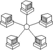
The Star Topology
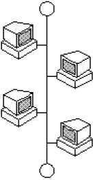
The Bus Topology
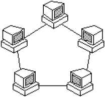
The Ring Topology
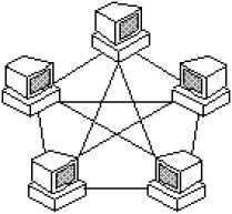
The Mesh Topology
- In the bus topology, all computers and devices are connected in series to a single linear cable called a trunk. The trunk is also known as a backbone or a segment. Both ends of the trunk must be terminated to stop the signal from bouncing back up the cable.
- In a ring topology, all computers and devices are connected to cable that forms a closed loop. On such networks there are no terminating ends; therefore, if one computer fails, the entire network will go down. Each computer on such a network acts like a repeater and boosts the signal before sending it to the next station. This type of network transmits data by passing a "token" around the network. If the token is free of data, a computer waiting to send data grabs it, attaches the data and the electronic address to the token, and sends it on its way. When the token reaches its destination computer, the data is removed and the token is sent on. Hence this type of network is commonly called a token ring network.
- In a mesh topology, all computers and devices are connected with many redundant interconnections between network nodes. There are two types of mesh topologies: full mesh and partial mesh.
- In a full mesh topology every computer or device has a link connecting it to every other computer or device in a network. Full mesh is very expensive to implement but yields the greatest amount of redundancy, so in the event that one of those nodes fails, network traffic can be directed to any of the other nodes. Full mesh is usually reserved for backbone networks.
- In a partial mesh topology some devices are organized in a full mesh scheme while others are only connected to one or two other devices in the network. Partial mesh topology is less expensive to implement and yields less redundancy than full mesh topology. Partial mesh is commonly found in peripheral networks connected to a full meshed backbone.
1.2.3 Basic Networking Devices
Network devices can be categorized based on their function relative to the OSI model. The main network devices are:
- Hubs and repeaters, which operate at the physical layer of the OSI model and basically transmit the incoming data (bits) out all other ports on the device. These devices are not aware of frames or packets; they amplify the signal and send out all ports. Repeaters do not break up broadcast or collision domains and are said to be protocol transparent because they are not aware of upper-layer protocols, such as IP, IPX, etc.
Bridges and Layer-2 switches, which operate at the data-link layer of the OSI model. Bridges learn the MAC layer addresses of each node of the segments and build tables of MAC addresses and ports, identifying which interface a particular MAC address is connected to. If the destination MAC address of an incoming frame is not in the table, bridges forward the frame to all ports except the port from which the frame came. If the destination MAC address is in the table, bridges forward the frame through the port to which the destination MAC address is attached if the destination MAC address is not on the same port from which the frame came, other wise the bridge filters (drops) the frame. Bridges are store-and-forward devices. They store the entire incoming frame and verify the checksum before forwarding the frame. If a checksum error is detected, the frame is discarded.
| Collision Domains | Broadcast Domains |
|---|---|
| A collision domain is a set of network interface cards (NICs) for which a frame sent by one NIC could result in a collision with a frame sent by any other NIC in the same collision domain. In a collision domain all devices on the network compete for the same bandwidth. | A broadcast domain is a set of NICs for which a broadcast frame sent by one NIC is received by all other NICs in the same broadcast domain. |
Switches use fast integrated circuits that reduce the latency common to bridges. Some switches have the capability to run in cut-through mode where the switch does not wait for the entire frame to enter its buffer; instead, it begins to forward the frame as soon as it finishes reading the destination MAC address. This increases the probability that error frames are propagated on the network because the frame is forwarded before the entire frame is buffered and checked for errors. Each port on a bridge or switch is a separate collision domain but all ports in a switch are in the same broadcast domain because bridges and switches do not control broadcasts. Instead they flood broadcasts out all ports.
Routers and Layer-3 switches, which operate in the network layer of the OSI model and make forwarding decisions based on network layer addresses, such as IP addresses. Routers define both collision and broadcast domains as each router interface is a separate broadcast domain that is defined by a separate subnetwork. Routers are protocol aware, which means that they are capable of forwarding packets of routable protocols such as IP, IPX, etc. Routers are configured to run routing protocols, such as Routing Information Protocol (RIP); Interior Gateway Routing Protocol (IGRP); Open shortest Path First (OSPF); Intermediate System-to-Intermediate System (IS-IS); Enhanced Interior Gateway Routing Protocol (EIGRP); and Border Gateway Protocol (BGP), to determine the best paths to a destination. Routers exchange information about destination networks and their interface status by using these routing protocols. Routers can also be configured manually with static routes.
| Layer-2 Switching and Routing |
|---|
| The major difference between Layer-2 switching and routing is that switching occurs at Layer 2 of the OSI reference model and routing occurs at Layer 3. Switches forward frames based on MAC address information while Routers forward packets based on logical addresses (IP address). |
LAN switches that are capable of running routing protocols and can communicate with routers as peers are called Layer-3 switches. Layer-3 switches off-load local traffic from wide-area network (WAN) routers by performing network-layer forwarding within the local-area networks (LANs). Both routers and Layer-3 switches make forwarding decisions based on IP addresses and not MAC addresses. Both participate in the exchange of route information based on the dynamic routing protocol they participate in.