1.1 The OSI Reference Model
The OSI Reference Model
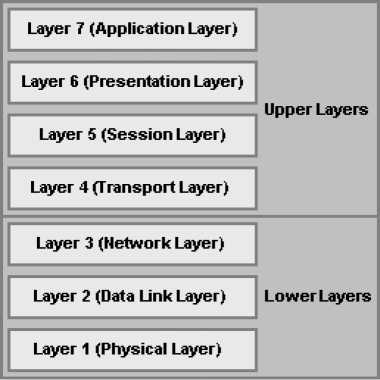
The Open Systems Interconnection (OSI) reference model was developed by the International Standards Organization (ISO) in 1984 to define network communications, and describe the flow of data on a network. The OSI reference model consists of seven layers that start with the physical connection and end with the application. As illustrated in the figure shown, the seven OSI layers are:
- The Physical Layer;
- The Data-Link Layer;
- The Network Layer;
- The Transport Layer;
- The Session Layer;
- The Presentation Layer; and
- The Application Layer.
Each layer performs particular functions and can have one ore more sublayers. The upper layers of the OSI reference model define functions focused on the application, while the lower three layers define functions to facilitate the transport and delivery of data from the source to the destination.
The upper layers of the OSI reference model, i.e., the Application Layer, the Presentation Layer, and the Session Layer, define functions focused on the application. The lower four layers, i.e., the Transport Layer, the Network Layer, the Data-Link Layer, and the Physical Layer, define functions focused on end-to-end delivery of the data.
1.1.1 The Physical Layer (Layer 1)
The Physical Layer deals with the physical characteristics of the transmission medium, such as signaling specifications, cable types and interfaces. It also describes voltage levels, physical data rates, and maximum transmission distances. In short, the physical layer deals with the electrical, mechanical, functional, and procedural specifications for the physical links between networked systems, and includes connectors, pins, use of pins, electrical currents, encoding, and light modulation are all part of different physical layer specifications.
Examples of physical layer specifications include:
- EIA/TIA-232 Interface;
- V.35 Interface;
- EIA/TIA-449 Interface;
- V.24 Interface;
- RJ-45 Interface;
- Non-Return-to-Zero Inverted (NRZI); and
- Bipolar with 8-Zero Substitution (B8ZS).
1.1.2 The Data-Link Layer (Layer 2)
The Data-Link Layer deals with the reliable transport of data across one particular link or medium. Data at the data link layer is encapsulated into frames. Data-link specifications deal with the sequencing of frames, flow control, synchronization, error notification, physical network topology, and physical addressing. At this layer, data is converted from frames into bits when it is sent across the physical media and is converted back into frames when it is received from the physical media. Bridges and switches operate at the data-link layer.
In the IEEE 802, the data link layer is subdivided into two sublayers, the Logical Link Control (LLC) sublayer and the Media Access Control (MAC) sublayer. The upper sublayer is called the Logical Link Control (LLC) sublayer and manages the communications between devices. The lower layer is called the Media Access Control (MAC) sublayer and manages protocol access to the physical media.
Examples of data-link layer technologies include:
- Frame Relay;
- Asynchronous Transport Mode (ATM);
- Synchronous Data Link Control (SDLC);
- High-level data-link control (HDLC);
- IEEE 802.3z and IEEE 802.3ab (Gigabit Ethernet);
- IEEE 802.3u (Fast Ethernet);
- Integrated Services Digital Network (ISDN);
- Point-to-Point Protocol (PPP);
- Spanning-Tree Protocol (STP).
1.1.3 The Network Layer (Layer 3)
The Network Layer deals with the routing of data, which is called packets at this layer, and defines the methods to facilitate this, including how routing works, logical addressing, how routes are learned; as well as how packets are fragmented into smaller packets to accommodate media with smaller maximum transmission unit (MTU) sizes.
Note: As you would expect, routers operate at this layer but they also perform Data-Link and Transport Layer functions. Thus a router is best described as a Layer2/3/4 device.
Examples network layer specifications include:
- Internet Protocol (IP);
- Routing Information Protocol (RIP);
- Open Shortest Path First (OSPF);
- Enhanced Interior Gateway Routing Protocol (EIGRP);
- Internetwork Packet Exchange (IPX); and
- Connectionless Network Protocol (CLNP).
Note: The functions of the IP and IPX protocols most closely match the OSI Network Layer (Layer 3) and are therefore called Layer 3 protocols.
1.1.4 The Transport Layer (Layer 4)
The Transport Layer performs several functions, including the choice of protocols. This layer provides reliable, transparent transport of data segments from upper layers. The most important Layer 4 functions are error recovery (retransmission) and flow control to prevent unnecessary congestion by attempting to send data at a rate that the network can accommodate, depending on the choice of protocols. Multiplexing of incoming data for different flows to applications on the same host is also performed. Messages are assigned a sequence number at the transmission end. At the receiving end the packets are reassembled, checked for errors, and acknowledged. Reordering of the incoming message when packets arrive out of order is also performed at this layer.
Examples transport layer specifications include:
- Transmission Control Protocol (TCP);
- Real-Time Transport Protocol (RTP);
- Sequenced Packet Exchange (SPX);
- User Datagram Protocol (UDP).
1.1.5 The Session Layer (Layer 5)
The Session Layer defines how to start, control, and end communication sessions between applications. Communication sessions consist of service requests and responses that occur between applications on different devices. This includes the control and management of multiple bidirectional messages so that the application can be notified if only some of a series of messages are completed. This allows the presentation layer to have a seamless view of an incoming stream of data. The management of sessions also involves the synchronization of dialog control by using checkpoints in the data stream.
Examples session layer specifications include:
- NetBIOS;
- Real-Time Control Protocol (RTCP);
- Session Control Protocol (SCP);
- H.323, H.245, and H.225; and
- Real-Time Control Protocol (RTCP).
1.1.6 The Presentation Layer (Layer 6)
The Presentation Layer ensures that data sent from a sending application on the source system is readable by the application layer on the destination system by providing data representation with a variety of coding and conversion functions. This includes defining the conversion of character representation formats, such as ASCII text, EBCDIC text, binary, BCD, and JPEG; data compression schemes; and encryption schemes. Voice coding schemes are specified at this layer.
Examples of presentation layer specifications include:
- Abstract Syntax Notation 1 (ASN.1);
- ASCII;
- Extended Binary Coded Decimal Interchange Code (EBCDIC);
- Motion Picture Experts Group (MPEG);
- Graphics Interchange Format (GIF);
- Joint Photographic Experts Group (JPEG);
- Tagged Image File Format (TIFF); and
- G.711, G.729a, G.726, G.728.
1.1.7 The Application Layer (Layer 7)
The Application Layer provides to network communication services to the end user or operating system. It interacts with software applications by identifying communication resources, determining network availability, and distributing information services. It also provides synchronization between the peer applications that reside on separate systems.
Examples application layer specifications include:
- Telnet
- File Transfer Protocol (FTP)
- HyperText Transfer Protocol (HTTP)
- Simple Mail Transfer Protocol (SMTP)
- Simple Network Management Protocol (SNMP)
- Network File System (NFS)
- Internet Browsers
1.1.8 Inter-OSI Layer Interaction
When a host receives a data transmission from another host on the network, that data is processed at each of the OSI layers to the next higher layer, in order to render the data transmission useful to the end-user. To facilitate this processing, headers and trailers are created by the sending host's software or hardware, that are placed before or after the data given to the next higher layer. Thus, each layer has a header and trailer, typically in each data packet that comprises the data flow. The sequence of processing at each OSI layer, i.e., the processing between adjacent OSUI layers, is as follows:
- The Physical Layer (Layer 1) ensures bit synchronization and places the received binary pattern into a buffer. It notifies the Data Link Layer (Layer 2) that a frame has been received after decoding the incoming signal into a bit stream. Thus, Layer 1 provides delivery of a stream of bits across the medium.
- The Data Link Layer (Layer 2) examines the frame check sequence (FCS) in the trailer to determine whether errors occurred in transmission, providing error detection. If an error has occurred, the frame is discarded. The current host examines data link address is examined to determine if the data is addressed to it or whether to process the data further. If the data is addressed to the host, the data between the Layer 2 header and trailer is handed over to the Network Layer (Layer 3) software. Thus, the data link layer delivers data across the link.
- The Network Layer (Layer 3) examines the destination address. If the address is the current host's address, processing continues and the data after the Layer 3 header is handed over to the Transport Layer (Layer 4) software. Thus, Layer 3 provides end-to-end delivery.
- If error recovery was an option chosen for the Transport Layer (Layer 4), the counters identifying this piece of data are encoded in the Layer 4 header along with acknowledgment information, which is called error recovery. After error recovery and reordering of the incoming data, the data is given to the Session Layer (Layer 5).
- The Session Layer (Layer 5) ensures that a series of messages is completed. The Layer 5 header includes fields signifying sequence of the packet in the data stream, indicating the position of the data packet in the flow. After the session layer ensures that all flows are completed, it passes the data after the Layer 5 header to the Presentation Layer (Layer 6) software.
- The Presentation Layer (Layer 6) defines and manipulates the data format of the data transmission. It converts the data to the proper format specified in the Layer 6 header. Typically, this header is included only for initialization flows, not with every data packet being transmitted. After the data formats have been converted, the data after the Layer 6 header is passed to the Application Layer (Layer 7) software.
- The Application Layer (Layer 7) processes the final header and examines the end-user data. This header signifies agreement to operating parameters by the applications on the two hosts. The headers are used to signal the values for all parameters; therefore, the header typically is sent and received at application initialization time only.
In addition to processing between adjacent OSI layers, the various layers must also interact with the same layer on another computer to successfully implement its functions. To interact with the same layer on another computer, each layer defines additional data bits in the header and, in some cases, trailer that is created by the sending host's software or hardware. The layer on the receiving host interprets the headers and trailers created by the corresponding layer on the sending host to determine how that layer's processing is being defined, and how to interact within that framework.