Section 1.2: TCP/IP and the OSI Reference Model
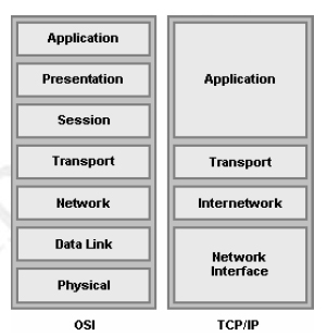
Figure 1.2: OSI and TCP/IP Models
As illustrated in Figure 1.2, the Transmission Control Protocol/Internet Protocol (TCP/IP) model consists of four layers, each of which can have several sublayers. These layers correlate roughly to layers in the OSI reference model and define similar functions. Some of the TCP/IP layers correspond directly with layers in the OSI reference model while others span several OSI layers. The four TCP/IP layers are:
- The TCP/IP Application Layer (refers to communications services to applications and is the interface between the network and the application. It is also responsible for presentation and controlling communication sessions. It spans the Application Layer, Presentation Layer and Session Layer of the OSI reference model. Examples include: HTTP, POP3, and SNMP.
- The TCP/IP Transport Layer defines several functions, including the choice of protocols, error recovery and flow control. The transport layer may provide for retransmission, i.e., error recovery, and may use flow control to prevent unnecessary congestion by attempting to send data at a rate that the network can accommodate, or it might not, depending on the choice of protocols. Multiplexing of incoming data for different flows to applications on the same host is also performed. Reordering of the incoming data stream when packets arrive out of order is included. It correlates with the Transport Layer of the OSI reference model. Examples include: TCP and UDP, which are called Transport Layer, or Layer 4, protocols.
- The TCP/IP Internetwork Layer defines end-to-end delivery of packets and defines logical addressing to accomplish this. It also defines how routing works and how routes are learned; and how to fragment a packet into smaller packets to accommodate media with smaller maximum transmission unit sizes. It correlates with the Network Layer of the OSI reference model. Examples include: IP and ICMP.
- The TCP/IP Network Interface Layer is concerned with the physical characteristics of the transmission medium as well as getting data across one particular link or medium. This layer defines delivery across an individual link as well as the physical layer specifications. It spans the Data Link Layer and Physical Layer of the OSI reference model. Examples include: Ethernet and Frame Relay.
1.2.1: The TCP/IP Protocol Architecture
TCP/IP defines a large collection of protocols that allow computers to communicate. Table 1.1 outlines the protocols and the TCP/IP architectural layer to which they belong. TCP/IP defines the details of each of these protocols in Requests For Comments (RFC) documents. By implementing the required protocols defined in TCP/IP RFCs, a computer that implements the standard networking protocols defined by TCP/IP can communicate with other computers that also use the TCP/IP standards.
Table 1.1: The TCP/IP Architectural Model and Protocols
| TCP/IP Architecture Layer | Protocols |
|---|---|
| Application | HTTP, POP3, SMTP |
| Transport | TCP, UDP |
| Internetwork | IP |
| Network interface | Ethernet, Frame Relay |
1.2.2: TCP/IP Data Encapsulation
The term encapsulation describes the process of putting headers and trailers around some data. A computer that needs to send data encapsulates the data in headers of the correct format so that the receiving computer will know how to interpret the received data. Data encapsulation with TCP/IP consists of five-steps:
Step 1: Create the application data and headers.
Step 2: Package the data for transport, which is performed by the transport layer (TCP or UDP). The Transport Layer creates the transport header and places the data behind it.
Step 3: Add the destination and source network layer addresses to the data, which is performed by the Internetwork Layer. The Internetwork Layer creates the network header, which includes the network layer addresses, and places the data behind it.
Step 4: Add the destination and source data link layer addresses to the data, which is performed by the Network Interface Layer. The Network Interface Layer creates the data link header, places the data behind it, and places the data link trailer at the end.
Step 5: Transmit the bits, which is performed by the Network Interface Layer. The Network Interface Layer encodes a signal onto the medium to transmit the frame.