Section 1.1: The OSI Reference Model
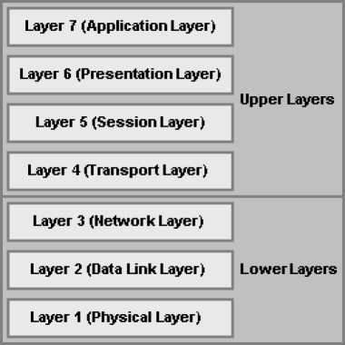
Figure 1.1: The OSI Reference Model
The OSI is the Open System Interconnection reference model for communications. As illustrated in Figure 1.1, the OSI reference model consists of seven layers, each of which can have several sublayers. The upper layers of the OSI reference model define functions focused on the application, while the lower three layers define functions focused on end-to-end delivery of the data.
- The Application Layer (Layer 7) refers to communications services to applications and is the interface between the network and the application. Examples include: Telnet, HTTP, FTP, Internet browsers, NFS, SMTP gateways, SNMP, X.400 mail, and FTAM.
- The Presentation Layer (Layer 6) defining data formats, such as ASCII text, EBCDIC text, binary, BCD, and JPEG. Encryption also is defined as a presentation layer service. Examples include: JPEG, ASCII, EBCDIC, TIFF, GIF, PICT, encryption, MPEG, and MIDI.
- The Session Layer (Layer 5) defines how to start, control, and end communication sessions. This includes the control and management of multiple bidirectional messages so that the application can be notified if only some of a series of messages are completed. This allows the presentation layer to have a seamless view of an incoming stream of data. The presentation layer can be presented with data if all flows occur in some cases. Examples include: RPC, SQL, NFS, NetBios names, AppleTalk ASP, and DECnet SCP
- The Transport Layer (Layer 4) defines several functions, including the choice of protocols. The most important Layer 4 functions are error recovery and flow control. The transport layer may provide for retransmission, i.e., error recovery, and may use flow control to prevent unnecessary congestion by attempting to send data at a rate that the network can accommodate, or it might not, depending on the choice of protocols. Multiplexing of incoming data for different flows to applications on the same host is also performed. Reordering of the incoming data stream when packets arrive out of order is included. Examples include: TCP, UDP, and SPX.
- The Network Layer (Layer 3) defines end-to-end delivery of packets and defines logical addressing to accomplish this. It also defines how routing works and how routes are learned; and how to fragment a packet into smaller packets to accommodate media with smaller maximum transmission unit sizes. Examples include: IP, IPX, AppleTalk DDP, and ICMP. Both IP and IPX define logical addressing, routing, the learning of routing information, and end-to-end delivery rules. The IP and IPX protocols most closely match the OSI network layer (Layer 3) and are called Layer 3 protocols because their functions most closely match OSI's Layer 3.
- The Data Link Layer (Layer 2) is concerned with getting data across one particular link or medium. The data link protocols define delivery across an individual link. These protocols are necessarily concerned with the type of media in use. Examples include: IEEE 802.3/802.2, HDLC, Frame Relay, PPP, ATM, and IEEE 802.5/802.2.
- The Physical Layer (Layer 1) deals with the physical characteristics of the transmission medium. Connectors, pins, use of pins, electrical currents, encoding, and light modulation are all part of different physical layer specifications. Examples includes: EIA/TIA-232, V.35, EIA/TIA-449, V.24, RJ-45, Ethernet, 802.3, 802.5, NRZI, NRZ, and B8ZS.
The upper layers of the OSI reference model, i.e., the Application Layer (Layer 7), the Presentation Layer (Layer 6), and the Session Layer (Layer 5), define functions focused on the application. The lower four layers, i.e., the Transport Layer (Layer 4), the Network Layer (Layer 3), the Data Link Layer (Layer 2), and the Physical Layer (Layer 1), define functions focused on end-to-end delivery of the data. As a Cisco Certified Network Associate, you will deal mainly with the lower layers, particularly the data link layer (Layer 2) upon which switching is based, and the network layer (Layer 3) upon which routing is based.
1.1.1: Interaction Between OSI Layers
When a host receives a data transmission from another host on the network, that data is processed at each of the OSI layers to the next higher layer, in order to render the data transmission useful to the end-user. To facilitate this processing, headers and trailers are created by the sending host's software or hardware, that are placed before or after the data given to the next higher layer. Thus, each layer has a header and trailer, typically in each data packet that comprises the data flow. The sequence of processing at each OSI layer, i.e., the processing between adjacent OSI layers, is as follows:
- The Physical Layer (Layer 1) ensures bit synchronization and places the received binary pattern into a buffer. It notifies the Data Link Layer (Layer 2) that a frame has been received after decoding the incoming signal into a bit stream. Thus, Layer 1 provides delivery of a stream of bits across the medium.
- The Data Link Layer (Layer 2) examines the frame check sequence (FCS) in the trailer to determine whether errors occurred in transmission, providing error detection. If an error has occurred, the frame is discarded. The current host examines data link address is examined to determine if the data is addressed to it or whether to process the data further. If the data is addressed to the host, the data between the Layer 2 header and trailer is handed over to the Network Layer (Layer 3) software. Thus, the data link layer delivers data across the link.
- The Network Layer (Layer 3) examines the destination address. If the address is the current host's address, processing continues and the data after the Layer 3 header is handed over to the Transport Layer (Layer 4) software. Thus, Layer 3 provides end-to-end delivery.
- If error recovery was an option chosen for the Transport Layer (Layer 4), the counters identifying this piece of data are encoded in the Layer 4 header along with acknowledgment information, which is called error recovery. After error recovery and reordering of the incoming data, the data is given to the Session Layer (Layer 5).
- The Session Layer (Layer 5) ensures that a series of messages is completed. The Layer 5 header includes fields signifying sequence of the packet in the data stream, indicating the position of the data packet in the flow. After the session layer ensures that all flows are completed, it passes the data after the Layer 5 header to the Presentation Layer (Layer 6) software.
- The Presentation Layer (Layer 6) defines and manipulates the data format of the data transmission. It converts the data to the proper format specified in the Layer 6 header. Typically, this header is included only for initialization flows, not with every data packet being transmitted. After the data formats have been converted, the data after the Layer 6 header is passed to the Application Layer (Layer 7) software.
- The Application Layer (Layer 7) processes the final header and examines the end-user data. This header signifies agreement to operating parameters by the applications on the two hosts. The headers are used to signal the values for all parameters; therefore, the header typically is sent and received at application initialization time only.
In addition to processing between adjacent OSI layers, the various layers must also interact with the same layer on another computer to successfully implement its functions. To interact with the same layer on another computer, each layer defines additional data bits in the header and, in some cases, trailer that is created by the sending host's software or hardware. The layer on the receiving host interprets the headers and trailers created by the corresponding layer on the sending host to determine how that layer's processing is being defined, and how to interact within that framework.