Section 5.3: Wireless Mobility
Mobility is the quality of being capable of movement or moving readily from place to place. 802.11 WLAN devices provide this kind of untethered freedom. But there's more to mobility than the lack of a network cable. Understanding how mobility is implemented in 802.11 arms you with the knowledge you need to support or facilitate mobile applications. Many terms describe mobility, but this chapter uses the terms mobility and roaming to describe the act of moving between access points (APs).
5.3.1: Wireless Roaming
Defining or characterizing the behavior of roaming stations involves two forms:
-Seamless roaming -Nomadic roaming
Seamless roaming is best analogized to a cellular phone call. For example, suppose you are using your cellular phone as you drive your car on the freeway. A typical global system for mobile (GSM) communications or time-division multiple access (TDMA) cell provides a few miles of coverage area, so it is safe to assume that you are roaming between cellular base stations as you drive. Yet as you roam, you do not hear any degradation to the voice call (that is what the cellular providers keep telling us). There is no noticeable period of network unavailability because of roaming. This type of roaming is deemed seamless because the network application requires constant network connectivity during the roaming process. Nomadic roaming is different from seamless roaming. Nomadic roaming is best described as the use of an 802.11-enabled laptop in an office environment. As an example, suppose a user of this laptop has network connectivity while seated at his desk and maintains connectivity to a single AP. When the user decides to roam, he undocks his laptop and walks over to a conference room. Once in the conference room, he resumes his work. In the background, the 802.11 client has roamed from the AP near the user's desk to an AP near the conference room. This type of roaming is deemed nomadic because the user is not using network services when he roams, but only when he reach his destination.
The distinction between whether a device roams within a roaming domain or between roaming domains has a large impact on application sessions. Figure 5-4 depicts a Layer 2 roaming domain. The roaming user can maintain application connectivity within the roaming domain and as long as its Layer 3 network address is maintained (does not change).
Figure 5-4. Roaming in a Layer 2 Roaming Domain
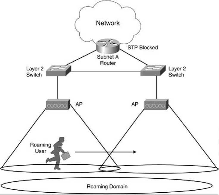
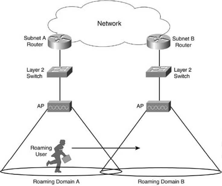
Figure 5-5 illustrates roaming across roaming domains. The roaming user is roaming from an AP on Subnet A to an AP on Subnet B. As a result, the Layer 3 network address must change to maintain Layer 3 connectivity on Subnet B. As the Layer 3 address changes, the station drops all application sessions. This scenario is described later in this chapter in the section, "Mobile IP Overview."
Figure 5-5. Roaming across Layer 2 Roaming Domains
5.3.1.1: Layer 2 Roaming
Now that you understand some of the characteristics of roaming, the technical discussion of how Layer 2 roaming operates can begin. To place some perspective on roaming, a sequence of events must transpire:
• The client must decide to roam- Roaming algorithms are vendor-specific (and proprietary) and rely on factors such as signal strength, frame acknowledgment, missed beacons, and so on.
• The client must decide where to roam- The client must figure out which AP to roam to. It can do so by scanning the medium for APs either before the decision to roam, which is a process called preemptive AP discovery, or after the decision to roam, which is a process called roam-time AP discovery.
• The client initiates a roam- The client uses 802.11 reassociation frames to associate to a new AP.
• The client can resume existing application sessions.
Roaming Algorithms:
The mechanism to determine when to roam is not defined by the IEEE 802.11 specification and is, therefore, left to vendors to implement. Although this issue posed an interoperability challenge early on with the first
802.11 products, vendors work together today to ensure basic interoperability. The fact that the algorithms are left to vendor implementation provide vendors an opportunity to differentiate themselves by creating new and better performing algorithms than their competitors. Roaming algorithms become a vendor's "secret sauce," and as a result are kept confidential.
It is safe to assume that issues such as signal strength, retry counters, missed beacons, and other MAC layer concepts discussed in Chapter 2 are included in the algorithms. For example, recall from Chapter 2 the discussion about distributed coordination function (DCF) operation. The binary exponential backoff algorithm for medium access incremen-ted the frame-retry counter if the frame could not be transmitted after a number of attempts. This process alerts the client that it has moved out of range of the AP. In this case, the roaming algorithm monitors the frame-retry counter to help with decision making.
Also, roaming algorithms must balance between fast roam time and client stability. For example, an extremely sensitive roaming algorithm might not tolerate a missed beacon or missed acknowledgment frame. The algorithm might view these occurrences as degra-dation in signal and initiate a roam. But it is normal for such occurrences in a BSS, and as a result, a stationary station might roam, even though it is stationary. Although roaming would be expeditious, the result is degraded network throughput for the user. Determining Where to Roam
Finding an AP to roam to is another mechanism that is vendor-specific. In general, there are two mechanisms for finding APs:
• Preemptive AP discovery
• Roam-time AP discovery
Each mechanism can employ one or both of the following mechanisms:
• Active scanning- The client actively searches for an AP. This process usually involves the client sending probe requests on each channel it is configured to use (channels 1 to 11 in North America) and waiting for probe responses from APs. The client then determines which AP is the ideal one to roam to.
• Passive scanning- The client does not transmit any frames but rather listens for beacon frames on each channel. The client continues to change channels at a set interval, just as with active scanning, but the client does not send probe requests.
Active scanning is the most thorough mechanism used to find APs because it actively sends out 802.11 probes across all channels to find an AP. It requires the client to dwell on a particular channel for a set length of time, roughly 10 to 20 milliseconds (ms) depending on the vendor, waiting for the probe response. With passive scanning, the client iterates through the channels slower than active scanning because it is listening for beacons that are sent out by APs at a set rate (usually 10 beacons per second). The client must dwell on each channel for a longer time duration to make sure it receives beacons from as many APs as possible for the given channel. The client looks for different information elements such as SSID, supported rates, and vendor proprietary elements to find an AP. Although it can be a faster mechanism to scan the medium, some elements are not transmitted, depending on AP configuration. For example, an adminis-trator might block the SSID name in the SSID IE from being transmitted in beacons, so the passive scanning client is unable to determine whether the AP is in the same roaming domain.
There is no ideal technique for scanning. Passive scanning has the benefit of not requiring the client to transmit probe requests but runs the risk of potentially missing an AP because it might not receive a beacon during the scanning duration. Active scanning has the benefit of actively seeking out APs to associate to but requires the client to actively transmit probes. Depending on the implementation for the 802.11 client, one might be better suited than the other. For example, many embedded systems use passive scanning as the preferred method, whereas 802.11 Voice over IP (VoIP) phones and PC client cards rely on active scanning. Preemptive AP Discovery
Preemptive roaming is the function that provides the client the ability to roam to a predeter-mined AP after the client has made the decision to roam. This process allows for minimal total roaming time, which reduces application impact from roaming. Preemptive roaming does not come without a penalty, however.
For the client to predetermine which AP to roam to, the client must scan for APs during normal nonroaming periods. When the client is scanning, the client must change channels to either listen for other APs or to actively probe.
• The client cannot receive data from the currently associated AP while it is channel scanning (active or passive)- If the AP sends data to the client while the client is channel scanning (meaning the client is on a different channel from the AP), the client will miss the data, requiring retransmission by the AP.
• The client application might experience throughput degradation- The client is unable to transmit data while channel scanning (active or passive), so any applications running on the client can experience throughput degradation.
A unique opportunity exists for power-save clients that allow them to use preemptive roaming without the two problems. Consider this scenario: A client is a power-save client. The client is capable of transitioning into low-power mode as needed. The client can signal to the AP that it is going into power-save mode, but instead of immediately transitioning to low-power mode, the client can channel scan (either actively or passively) all or a select number of channels and look for new APs. The current AP queues frames destined for the client until the client "wakes up," so the client does not experience data loss due to channel scanning. The client can also queue frames targeted for transmission until channel scanning is complete, eliminating data loss in that respect as well.
This solution does reduce the effectiveness of a power-save operation, because the client radio is active during channel scanning instead of in low-power mode, and client applications might experience some delay because frames are queued in a transmit queue.
Preemptive AP discovery can be undermined by a fast-moving client. A client might move at a rate where the predetermined AP is no longer the ideal AP to roam to, causing an increase in the frequency of roaming decisions and an overall degradation in application throughput.
Roam-Time AP Discovery
The other option for AP discovery is to look for an AP after the decision to roam has been made. This process is similar to the process a client goes through on initiation power up, except that the association message the client sends to the new AP is actually a reassociation frame.
Roam-time AP discovery does not have the overhead of preemptive roaming during non-roaming times, but because the client does not know which AP to reassociate to, there can be a larger time penalty during the roaming process.
Layer 2 Roaming Process:
The act of roaming includes more processes than just finding a new AP to communicate with. The following list includes some of the tasks for Layer 2 roaming:
1. The previous AP must determine that the client has roamed away from it.
2. The previous AP should buffer data destined for the roaming client.*
3. The new AP should indicate to the previous AP that the client has successfully roamed. This step usually happens via a unicast or multicast packet from the old AP to the new AP with the source MAC address set to the MAC of the roaming client.*
4. The previous AP should send the buffered data to the new AP.
5. The previous AP must determine that the client has roamed away from it.
6. The AP must update MAC address tables on infrastructure switches to prevent the loss of data to the roaming client.
* Tasks are not mandatory because they are not specified in the 802.11 standard.
5.3.1.2: Layer 3 Roaming Layer 3 Roaming
Layer 3 mobility is a superset of Layer 2 mobility. An 802.11 client must perform a Layer 2 roam, including AP discovery, before it can begin a Layer 3 roam. This section focuses on issues surrounding Layer 3 roaming, specifically with the IP Protocol and Mobile IP extensions (RFC 2002). It covers the following topics:
• Roaming between roaming domains
• A Mobile IP overview
Roaming Between Roaming Domains
As previously discussed, a roaming domain is defined as APs that are in the same broadcast domain and configured with the same SSID. Stated another way, a client can only roam between APs in the same VLAN and with the same SSID. As WLAN deployments expand within an organization, roaming domains might need to scale beyond a single Layer 2 VLAN.
Consider the following scenario: Company A has a four-story building in which it has deployed a WLAN. The initial deployment was small, and the WLAN was a single Class C subnet for the entire building. This setup created a roaming domain across all four floors of the building. As time progressed, the number of users increased to the point that the subnet is full, and performance is degrading because of increased broadcast traffic.
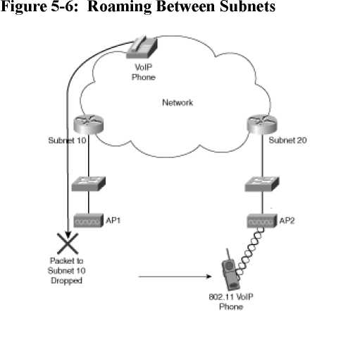
Company A decides to follow its desktop subnet model and use a single subnet per floor for the WLAN. This setup introduces complications because now the roaming domains are restricted to a floor, not the entire building as before. With the new subnet model in place, application persistence when roaming across floors is lost. The application most impacted is Company A's wireless VoIP devices. As users move between the floors (and subnets) on their wireless phones, they drop their calls when they roam. Figure 5-6 illustrates this scenario. In this figure, an 802.11 VoIP phone is connected to a wired VoIP phone. As the user roams from AP1 on Subnet 10 to AP2 on Subnet 20, the session drops because the roaming user is now on a different subnet.
The scenario described for Company A is common. Many applications require persistent connections and drop their sessions as a result of inter-VLAN roaming. To provide session persistence, you need a mechanism to allow a station to maintain the same Layer 3 address while roaming throughout a multi-VLAN network. Mobile IP provides such a mechanism, and it is the standards-based, vendor-interoperable solution to Layer 3 roaming for WLANs.
A Mobile IP-enabled network has these key components:
• Mobile node (MN)- The MN is the roaming station.
• Home agent (HA)- The HA exists on routers or Layer 3 switches and ensures that a roaming MN receives its IP packets.
• Foreign agent (FA)- The FA exists on router or Layer 3 switches and aids the MN notifying the HA of the new MN location by receiving packets from the HA destined for the MN.
• Care-of address (CoA)- The CoA is a locally attached router that receives packets sent by the HA, destined for the MN.
• Co-located care-of address (CCoA)- A CoA that exists on the mobile node itself.
Roaming in a Mobile IP-aware network involves the following steps:
1. A station is on its home subnet if the station's IP address belongs to the subnet of the HA.
2. As the MN roams to a foreign subnet, the MN detects the presence of the FA and registers with the FA or with the MN CCoA.
3. The FA or MN CCoA communicates with the HA and establishes a tunnel between the HA and a CoA for the MN.
4. Packets destined to the MN are sent to the HA (via normal IP routing), as shown in Figure 5-9.
5. The HA forwards the packets via the tunnel to the MN.
6. Any packets the MN transmits are sent via the FA as if the MN were local on the subnet, as shown in Figure 5-10. (A "reverse tunnel" mode is available when the edge routers use ingress packet filtering.)