Section 3.3: VLAN Trunks
At the access layer, end user devices connect to switch ports that provide simple connectivity to a single VLAN each. The attached devices are unaware of any VLAN structure.
A trunk link can transport more than one VLAN through a single switch port. A trunk link is not assigned to a specific VLAN. Instead, one or more active VLANs can be transported between switches using a single physical trunk link. Connecting two switches with separate physical links for each VLAN is also possible. Cisco supports trunking on both Fast Ethernet and Gigabit Ethernet switch links, as well as aggregated Fast EtherChannel links and Gigabit EtherChannel links.
3.3.1: VLAN Frame Identification
To distinguish between traffic belonging to different VLANs on a trunk link, the switch must be able to identifying each frame with the appropriate VLAN. Frame identification, or tagging is one identification method that trunk links have. Frame identification assigns a unique user-defined ID to each frame transported on a trunk link. As each frame is transmitted over a trunk link, a unique identifier is placed in the frame header. As each switch along the way receives these frames, the identifier is examined to determine to which VLAN the frames belong. If frames must be transported out to another trunk link, the VLAN identifier is retained in the frame header. If frames are destined out an access link, the switch removes the VLAN identifier before transmitting the frames to the end station. Therefore, all traces of VLAN association are hidden from the end station. VLAN identification can be performed using several methods. Each uses a different frame identifier mechanism, and some are suited for specific network media. These include:
• Inter-Switch Link (ISL) protocol, a Cisco proprietary method for preserving the source VLAN identification of frames passing over a trunk link and is primarily used for Ethernet media, although Cisco has included provisions to carry Token Ring, FDDI, and ATM frames over Ethernet ISL. ISL performs frame identification in Layer 2 by encapsulating each frame between a header and trailer. Any Cisco switch or router device configured for ISL can process and understand the ISL VLAN information. ISL.
• IEEE 802.1Q protocol, a non-propriety method for preserving VLAN identification of frames passing over a trunk link and thus allows VLAN trunks to exist and operate between equipment from different vendors. The IEEE 802.1Q standard defines architecture for VLAN use, services provided with VLANs, and protocols and algorithms used to provide VLAN services. Like Cisco ISL, IEEE 802.1Q can be used for VLAN identification with Ethernet trunks. Instead of encapsulating each frame with a VLAN ID header and trailer, 802.1Q embeds its tagging information within the Layer 2 frame. 802.1Q also introduces the concept of a native VLAN on a trunk. Frames belonging to this VLAN are not encapsulated with tagging information. In the event that an end station is connected to an 802.1Q trunk link, the end station will be able to receive and understand only the native VLAN frames.
Note: Both ISL and 802.1Q tagging methods add to the length of an Ethernet frame. ISL adds a total of 30 bytes to each frame, while 802.1Q adds 4 bytes. Because Ethernet frames cannot exceed 1518 bytes, the additional VLAN tagging information can cause the frame to be too large.
• IEEE 802.10, is another Cisco proprietary method for transporting VLAN information inside the standard IEEE 802.10 FDDI frame. The VLAN information is carried in the Security Association Identifier (SAID) field of the 802.10 frame.
3.3.2: Dynamic Trunking Protocol
Trunk links on Catalyst switches can be manually configured for either ISL or 802.1Q mode. However, Cisco has a proprietary point-to-point protocol called Dynamic Trunking Protocol (DTP) that will negotiate a common trunking mode between two switches if both switches belong to the same VLAN Trunking
Protocol (VTP) management domain. DTP is available in Catalyst supervisor engine software Release 4.2 and later. However, routers cannot participate in DTP negotiation, therefore, DTP negotiation should be disabled if a switch has a trunk link connected to a router.
3.3.3: VLAN Trunk Configuration
By default, all switch ports are non-trunking and operate as access links. There are a number commands that can be used to configure VLAN trunks on both an IOS-based and CLI-based switch.
On an IOS-based switch, you would use the following set of commands to create a VLAN trunk link:
Switch(config)# interface interface module_number/port_number Switch(config-if)# switchport mode trunk
Switch(config-if)# switchport trunk encapsulation { isl | dot1q } Switch(config-if)# switchport trunk allowed vlan remove vlan_list Switch(config-if)# switchport trunk allowed vlan add vlan_list
These commands place the switch port into trunking mode, using the encapsulation specified as either isl or dot1q. The last two commands define which VLANs can be trunked over the link. To view the trunking status on a switch port, use the following command:
show interface int module_number/port_number switchport
On a CLI-based switch, you would use the set trunk CLI-based commands to create a VLAN trunk link. This command sets the trunking mode and any mode negotiation. The set trunk command can be used to identify the VLANs that will be transported over the trunk link. The full syntax for this command:
Switch(enable) set trunk module_number/port_number [ on | off | desirable | auto | nonegotiate ] vlan_range [ isl | dot1q | dot10 | lane | negotiate]
By default, a switch will transport all VLANs over a trunk link, even if a VLAN range is specified in the set trunk command. Therefore, to remove VLANs from a trunk link, use the following command:
Switch(enable) clear trunk module_number/port_number vlan_range
If VLANs need to be added back to the trunk, they can be specified as the vlan_range in the set trunk command.
The options for setting the trunking mode with the set trunk command are:
• on, which places the port in permanent trunking mode.
• off, which places the port in permanent non-trunking mode.
• desirable, which will cause the port to actively attempt to convert the link into trunking mode.
• auto, which will allow the port to convert the link into trunking mode and negotiate trunking.
• nonegotiate, which places the port in permanent trunking mode, but no DTP frames are generated for negotiation.
The trunk encapsulation or identification mode is specified at the end of the set trunk command. These values are:
• isi, which specifies that the Cisco ISL protocol should be used. This protocol is the default, if no value is specified.
• dotiq, which specifies that the IEEE 802.1Q standard protocol should be used.
• dotio, which specifies that the IEEE 802.10 protocol should be used (only on an FDDI switch port).
• negotiate, which specifies that Fast and Gigabit Ethernet ports must negotiate to select either ISL or IEEE 802.1Q.
To view and verify the trunk configuration on a switch, use the show trunk [ module_number/port_number ] command.
3.3.4: Private VLANs
Fom the Cisco perspective, PVLANs are a tool that allows segregating traffic at Layer 2 (L2) turning a broadcast segment into a non-broadcast multi-access-like segment. Traffic that comes to a switch from a promiscuous port (that is, a port that is capable of forwarding both primary and secondary VLANs) is able to go out on all the ports that belong to the same primary VLAN. Traffic that comes to a switch from a port mapped to a secondary VLAN (it can be either an isolated, a community, or a two-way community VLAN) can be forwarded to a promiscuous port or a port belonging to the same community VLAN. Multiple ports mapped to the same isolated VLAN cannot exchange any traffic.
The following image shows the concept.
Private VLANs:
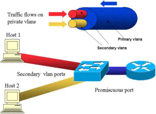
The primary VLAN is represented in blue; the secondary VLANs are represented in red and yellow. Host-1 is connected to a port of the switch that belongs to the secondary VLAN red. Host-2 is connected to a port of the switch that belongs to the secondary VLAN yellow.
When a host is transmitting, the traffic is carried in the secondary VLAN. For example, when Host-2 transmits, its traffic goes on VLAN yellow. When those hosts are receiving, the traffic comes from the VLAN blue, which is the primary VLAN.
The ports where routers and firewalls are connected are promiscuous ports because those ports can forward traffic coming from every secondary VLAN defined in the mapping as well as the primary VLAN. The ports connected to each hosts can only forward the traffic coming from the primary VLAN and the secondary VLAN configured on that port.
The drawing represents the private VLANs as different pipes that connect routers and hosts: the pipe that bundles all the others is the primary VLAN (blue), and the traffic on VLAN blue flows from the routers to the hosts. The pipes internal to the primary VLAN are the secondary VLANs, and the traffic traveling on those pipes is from the hosts towards the router.
As the image is showing, a primary VLAN can bundle one or more secondary VLANs.
Earlier in this document we said PVLANs help enforce the proper trust model by simply ensuring the segregation of hosts within a common segment. Now that we know more about Private VLANs, let us see how this can be implemented in our initial DMZ scenario. Servers are not supposed to talk to each other, but they still need to talk to the firewall or router to which they are connected. In this case, servers should be connected to isolated ports while routers and firewalls should be attached to promiscuous ports. By doing this, if one of the servers is compromised, the intruder won't be able to use the same server to source an attack to another server within the same segment. The switch will drop any packet at wire speed, without any performance penalty.
Another important note is that this kind of control can only be implemented at the L2 device because all servers belong to the same subnet. There is nothing a firewall or router can do since servers will try to communicate directly. Another option is to dedicate a firewall port per server, but this is likely too expensive, difficult to implement, and does not scale.
3.3.4.1: Configuring Private VLANs
Private VLANs provide a mechanism to control which devices can communicate within a single subnet. The private VLAN uses isolated and community secondary VLANs to control how devices communicate. The secondary VLANs are assigned to the primary VLAN, and ports are assigned to the secondary VLANs. Ports in an isolated VLAN cannot communicate with any device in the VLAN other than the promiscuous port. Ports configured in a community VLAN can communicate with other ports in the same community and the promiscuous port. Ports in different communities cannot communicate with one another. To configure private VLANs, use the following steps.
1. Set VTP transparent mode:
|
COS |
set vtp mode transparent |
|
IOS |
(privileged) vlan database (vlan_database) vtp transparent |
You must configure VTP to transparent mode before you can create a private VLAN. Private VLANs are configured in the context of a single switch and cannot have members on other switches. Private VLANs also carry TLVs that are not known to all types of Cisco switches.
2. Create the primary private VLAN:
|
COS |
set vlan primary number pvlan-type primary |
|
IOS |
(global) vlan primary number (vlan-config) private-vlan primary |
You must first create a primary private VLAN. The number of the primary VLAN is used in later steps for binding secondary VLANs and mapping promiscuous ports.
3. Create isolated and community VLANs:
|
COS |
set vlan secondary number pvlan-type [isolated | community | twoway- community] |
|
IOS |
(global) vlan secondary number (vlan-config) private-vlan [isolated | community] |
Configure isolated or community secondary VLANs for assignment of ports and control of the traffic. The secondary number for each of these VLANs must be unique from one another and the primary number. Members of an isolated VLAN can only communicate with the promiscuous port(s) mapped in Step 6, whereas members of a community VLAN can communicate with members of the same community and the promiscuous ports. A two-way community acts like a regular community, but has the additional aspect of allowing access control lists to check traffic going to and from (two ways) the VLAN and provides enhanced security within a private VLAN.
4. Bind isolated and community VLANs to the primary VLAN:
|
COS |
set pvlan primary number secondary number |
|
IOS |
(global) vlan primary number (vlan-config) private-vlan association secondary number list [add secondary number list] |
This command associates or binds the secondary VLANs to the primary VLAN. For the IOS command, the add option allows other VLANs to be associated in the future.
5. Place ports into the isolated and community VLANs:
|
COS |
set pvlan primary number secondary number mod/port [sc0] |
|
IOS |
(global) interface type mod/port (interface) switchport (interface) switchport mode private-vlan host (interface) switchport mode private-vlan host-association primary number secondary number |
After you have created and associated the primary and secondary VLANs, you must assign ports to that VLAN. For COS switches, you can add the sc0 interface to the private VLAN as well.
6. Map the isolated and community VLANs to promiscuous port(s):
|
COS |
set pvlan mapping primary number secondary number mod/port |
|
IOS |
(global) interface type mod/port (interface) switchport (interface) switchport mode private-vlan promiscuous |
(interface) switchport mode private-vlan
mapping primary_number
secondarynumber
a promiscuous Card (MSFC)
After you have assigned ports to the secondary VLANs, you must map the VLANs to port for access outside of the isolated or community VLAN.
7. (Optional) Map the isolated and community VLANs a Multilayer Switch Feature interface:
|
COS |
set pvlan mapping primary number secondary number 15/1 session 15 (privileged)config t (global)interface vlan primary number (interface)ip address address mask |
|
IOS |
(global) interface primary number (interface) ip address address mask (interface) private-vlan mapping primary number secondary number |
If your switch has an MSFC, you can map the private VLANs to the MSFC. For a switch running COS, you map the VLAN to port 15/1 (or 16/1 for the MSFC in slot 2), and then configure the IP address on the VLAN interface with the number of the primary VLAN. For an IOS switch, you go to the VLAN interface with the primary number, and then map the primary and secondary VLANs to that port.
Verifying Private VLAN Operation
After configuring private VLANs, use the following command to verify operation:
|
COS |
show pvlan number show pvlan mapping show pvlan capability mod/port |
|
IOS |
show vlan private-vlan [type] show interface private-vlan mapping show interface type mod/port switchport |
NOTE: A number of guidelines and restrictions apply to private VLANs. For a complete list of these items, go to http://www.cisco.com/univercd/cc/td/doc/product/lan/cat6000/sw_7_2/confg_gd/vlans.htm#xtocid21.