Section 1.3: Switching Technologies
Switching technologies are crucial to the new network design. To understand switching technologies and how routers and switches work together, you must understand the Open Systems Interconnection (OSI) model.
1.3.1: Open Systems Interconnection Model
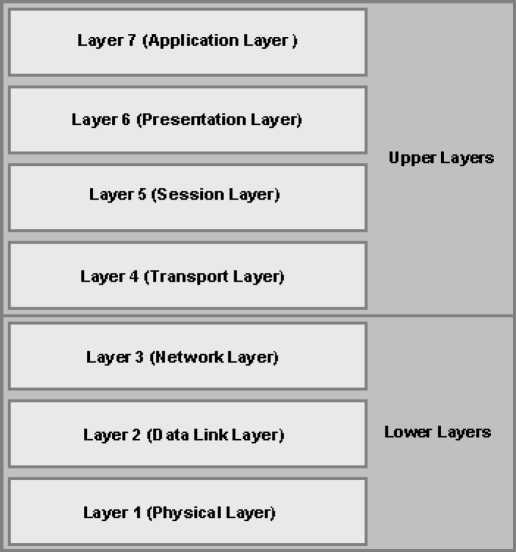
Figure 1.1: The Open System Interconnection (OSI Model)
The OSI model has seven layers (see Figure 1.1), each of which specifies functions that allow data to be transmitted from one host to another on an internetwork. The OSI model is the cornerstone for application developers to write and create networked applications that run on an internetwork. What is important to network engineers and technicians is the encapsulation of data as it is transmitted on a network.
1.3.1.1: Data Encapsulation
Data encapsulation is the process by which the information in a protocol is wrapped, in the data section of another protocol. In the OSI reference model, each layer encapsulates the layer immediately above it as the data flows down the protocol stack. The logical communication that happens at each layer of the OSI reference model does not involve many physical connections because the information each protocol needs to send is encapsulated in the layer of protocol information beneath it. This encapsulation produces a set of data called a packet.
Each layer communicates only with its peer layer on the receiving host, and they exchange Protocol Data Units (PDUs). The PDUs are attached to the data at each layer as it traverses down the model and is read only by its peer on the receiving side.
Table 1.1: OSI Encapsulation
| OSI Layer | Protocol Data Unit | Device |
|---|---|---|
| Transport | TCP Segment | TCP Port |
| Network | Packet | Router |
| Data Link | Frame | Bridge/switch |
Starting at the Application layer, data is converted for transmission on the network, and then encapsulated in Presentation layer information. The Presentation layer receives this information, and hands the data to the Session layer, which is responsible for synchronizing the session with the destination host. The Session layer then passes this data to the Transport layer, which transports the data from the source host to the destination host. However, before this happens, the Network layer adds routing information to the packet. It then passes the packet on to the Data Link layer for framing and for connection to the Physical layer. The Physical layer sends the data as bits (1s and 0s) to the destination host across fiber or copper wiring. When the destination host receives the bits, the data passes back up through the model, one layer at a time. The data is deencapsulated at each of the OSI model's peer layers.
The Network layer of the OSImodel defines a logical network address. Hosts and routers use these addresses to send information from host to host within an internetwork. Every network interface must have a logical address, typically an IP address.
1.3.1.2: Layer 2 Switching
Layer 2 (Data Link) switching is hardware based, which means it uses the Media Access Control (MAC) address from the host's network interface cards (NICs) to filter the network. Switches use Application-Specific Integrated Circuits (ASICs) to build and maintain filter tables. Layer 2 switching provides hardware-based bridging; wire speed; high speed; low latency; and low cost. It is efficient because there is no modification to the data packet, only to the frame encapsulation of the packet, and only when the data packet is passing through dissimilar media, such as from Ethernet to FDDI.
Layer 2 switching has helped develop new components in the network infrastructure. These are:
• Server farms - servers are no longer distributed to physical locations because virtual LANs can be created to create broadcast domains in a switched internetwork. This means that all servers can be placed in a central location, yet a certain server can still be part of a workgroup in a remote branch.
• Intranets allow organization-wide client/server communications based on a Web technology.
However, these new components allow more data to flow off of local subnets and onto a routed network, where a router's performance can become the bottleneck.
Layer 2 switches have the same limitations as bridge networks. They cannot break up broadcast domains, which can cause performance issues and limits the size of the network. Thus, broadcast and multicasts, along with the slow convergence of spanning tree, can cause major problems as the network grows. The table below briefly summarizes the differences between Layer 2 switching and bridges
TABLE 1.2: Differences between Switches and Bridges
| Operation / Occurrences | Switches | Bridges |
|---|---|---|
| Ports | Numerous | Maximum of 16 |
| Filters | Hardware based | Software based |
| Spanning Tree numbers | Many occurrences | One occurrence |
Because of these problems, layer 2 switches cannot completely replace routers in the internetwork. They can however be used for workgroup connectivity and network segmentation. When used for workgroup connectivity and network segmentation, layer 2 switches allows you to create a flatter network design and one with more network segments than traditional 10BaseT shared networks.
Address learning occurs when Layer 2 switches and bridges learn the hardware addresses of all devices on an internetwork and enters it into a MAC database. A switch is in essence a multiport transparent bridge. Frame forwarding is based on the MAC addresses that each frame has. A switch forwards a frame when it knows the destination device's location.
The MAC filtering table has nothing in it when a switch is powered. Once a frame is received from a device, the switch retains information on which interface the device is located on. It inserts the source address into the MAC filter table. Since the device's location is unknown at this stage, the network is flooded with the frame.
When a device replies and returns a frame, the switch gets that frame's source address and inserts the MAC address in the MAC database. This source address is connected with the interface on which the frame was initially received. At this point, the switch has two MAC addresses in the MAC filtering table and the devices can create a point-to-point connection. Frames are transmitted just between the two devices.
Forwarding and Filtering Decisions is the procedure that a switch uses to establish which ports to forward a frame out of. In addition, the Layer 2 switch uses the MAC filter table to filter received frames. When a switch port receives a frame, it places the frame into one of its ingress queues. The switch then has to decide on the forwarding policies as well find the egress switch port. These decision processes are outlined below.
• L2 Forwarding Table: The destination hardware address is utilized as an input key and placed into the Content Addressable Memory (CAM). The egress switch port and its fitting VLAN ID are obtained from the address table if it is listed there. The frame is transmitted out on the correct exit interface.
• Security Access Control Lists (ACLs): The Ternary Content Addressable Memory (TCAM) holds ACLs that can be utlized to single out frames. Frames are identified on their MAC addresses, IP addresses, Layer 4 port numbers and protocol types when the frame is not an IP frame.
• QoS ACLs: These ACLs can be utilized to categorize received frames in relation to quality of service (QoS) parameters. In this manner, the extent of traffic flows can be controlled and QoS parameters in outbound frames can be noted.
Another function that Layer 2 switching is responsible for is Loop Avoidance. Network loops takes place when there are multiple links between switches that were established for redundancy. Although this can help to prevent network failures, redundant links can cause severe problems. These are noted below
• Broadcast Storms occur when switches continuously flood broadcasts all through the network. Loop avoidance help to avoid this situation
• Multiple frames can turn up from different links concurrently and cause Multiple Frame Copies. The switch would not know the location of device. Thrashing the MAC table happens when a switch cannot send a frame because it is continuously updating the MAC table
1.3.1.3: Layer 3 Switching
The difference between a layer 3 (Network) switch and a router is the way the administrator creates the physical implementation. In addition, traditional routers use microprocessors to make forwarding decisions, whereas the layer 3 switch performs only hardware-based packet switching. Layer 3 switches can be placed anywhere in the network because they handle high-performance LAN traffic and can cost-effectively replace routers. Layer 3 switching is all hardware-based packet forwarding, and all packet forwarding is handled by hardware ASICs. Furthermore, Layer 3 switches provide the same functionally as the traditional router. These are:
Routers
Routers and layer 3 switches are similar in concept but not design. Like bridges, routers break up collision domains but they also break up broadcast/multicast domains. The benefits of routing include:
• Break up of broadcast domains;
• Multicast control;
• Optimal path determination;
• Traffic management;
• Logical (layer 3) addressing; and
• Security.
Routers provide optimal path determination because the router examines every packet that enters an interface and improves network segmentation by forwarding data packets to only a known destination network. If a router does not know about a remote network to which a packet is destined, it will drop the packet. Because of this packet examination, traffic management is obtained. Security can be obtained by a router reading the packet header information and reading filters defined by the network administrator.
• Determine paths based on logical addressing;
• Run layer 3 checksums on header only;
• Use Time to Live (TTL);
• Process and responds to any option information;
• Can update Simple Network Management Protocol (SNMP) managers with Management Information Base (MIB) information; and
• Provide Security.
The benefits of Layer 3 switching include:
• Hardware-based packet forwarding;
• High-performance packet switching;
• High-speed scalability;
• Low latency;
• Lower per-port cost;
• Flow accounting;
• Security; and
Quality of service (QoS).
1.3.1.4: Layer 4 Switching
Layer 4 (Transport) switching is considered a hardware-based layer 3 switching technology. It provides additional routing above layer 3 by using the port numbers found in the Transport layer header to make routing decisions. These port numbers are found in Request for Comments (RFC) 1700 and reference the upper-layer protocol, program, or application.
The largest benefit of layer 4 switching is that the network administrator can configure a layer 4 switch to prioritize data traffic by application, which means a QoS can be defined for each user. However, because users can be part of many groups and run many applications, the layer 4 switches must be able to provide a huge filter table or response time would suffer. This filter table must be much larger than any layer 2 or 3 switch. A layer 2 switch might have a filter table only as large as the number of users connected to the network while a layer 4 switch might have five or six entries for each and every device connected to the network. If the layer 4 switch does not have a filter table that includes all the information, the switch will not be able to produce wire-speed results.
1.3.1.5: Multi-Layer Switching (MLS)
Multi-layer switching combines layer 2 switching, layer 3 switching, and layer 4 switching technologies and provides high-speed scalability with low latency. It accomplishes this by using huge filter tables based on the criteria designed by the network administrator. Multi-layer switching can move traffic at wire speed while also providing layer 3 routing. This can remove the bottleneck from the network routers. Multi-layer switching can make routing/switching decisions based on:
• The MAC source/destination address in a Data Link frame;
• The IP source/destination address in the Network layer header;
• The Protocol filed in the Network layer header; and
• The Port source/destination numbers in the Transport layer header.
Two types of MLS are supported by catalyst switches:
• Route caching needs a switch engine (SE) and a route processor (RP). The RP processes a traffic flow's first packet in order to establish the destination, while the SE inserts an entry in its MLS cache to store the relevant destination. These SE uses these entries when sending the next packets in the same traffic flow. Route caching is also known as demand-based switching, Netflow LAN switching and flow-based switching.
• With Topology-based switching, which is also known as Cisco Express Forwarding (CEF), Layer 3 routing data creates and preloads a database of the whole network topology. This database is checked when forwarding packets.
Packets entering the switch port are located in the ingress queue, and are then extracted and examined for Layer 2 and Layer 3 destination. A decision process is performed to determine the destination for the packet and the forwarding policies:
• L2 Forwarding Table: The destination MAC address is utilized like an input key to the CAM table. When the frame has a Layer 3 packet, the only action taken is to process the packet at that layer.
• L3 Forwarding Table: The destination IP address is utilized as an input key and checked against the FIB table. The FIB table also holds the egress switch port with its fitting VLAN ID, and each entry's Layer 2 MAC address.
• Security Access Control Lists (ACLs): The Ternary Content Addressable Memory (TCAM) holds ACLs that can be utlized to single out frames. A decision on whether to forward a packet is done as a single table lookup.
• QoS ACLs: These ACLs can be utilized to categorize received frames in relation to quality of service (QoS) parameters. Packet categorization and marking can be done as a single table lookups in the QoS TCAM.
The following are excluded from MLS because they cannot be directly forwarded by CEF:
• Cisco Discovery Protocol packets
• ARP requests and replies
• IP packets that needs a reply from a router
• Routing protocol updates
• IP broadcasts to be passed on as unicast
• Packets setting off Network Address Translation (NAT)
• Packets that require encryption
1.4: The Cisco Hierarchical Model
When used properly in network design, a hierarchical model makes networks more predictable. It helps to define and expect at which levels of the hierarchy we should perform certain functions. The hierarchy requires that you use tools like access lists at certain levels in hierarchical networks and must avoid them at others. In short, a hierarchical model helps us to summarize a complex collection of details into an understandable model. Then, as specific configurations are needed, the model dictates the appropriate manner for in which they are to be applied.
The Cisco hierarchical model is used to design a scalable, reliable, cost-effective hierarchical internetwork. Cisco defines three layers of hierarchy: the core layer; the distribution layer; and the access layer. These three layers are logical and not necessarily physical. They are thus not necessarily represented by three separate devices. Each layer has specific responsibilities.
1.4.2.1: Core Layer
At the top of the hierarchy is the core layer. It is literally the core of the network and is responsible for switching traffic as quickly as possible. The traffic transported across the core is common to a majority of users. However, user data is processed at the distribution layer, and the distribution layer forwards the requests to the core, if needed. If there is a failure in the core, every all user can be affected; therefore, fault tolerance at this layer is critical.
As the core transports large amounts of traffic, you should design the core for high reliability and speed. You should thus consider using data-link technologies that facilitate both speed and redundancy, such as FDDI, FastEthernet (with redundant links), or even ATM. You should use routing protocols with low convergence times. You should avoid using access lists, routing between virtual LANs (VLANs), and packet filtering. You should also not use the core layer to support workgroup access and upgrade rather than expand the core layer if performance becomes an issue in the core.
The following Cisco witches are recommended for use in the core:
• The Catalyst 6500 Series, which are designed to address the need for gigabit port density, high availability, and multi-layer switching for the core layer backbone and server-aggregation environments. These switches use the Cisco IOS to utilize the high speeds of the ASICs, which allows the delivery of wire-speed traffic management services end to end.
• The Catalyst 8500, which provides high performance switching. It uses Application-Specific Integrated Circuits (ASICs) to provide multiple-layer protocol support including Internet Protocol (IP), IP multicast, bridging, and Cisco Assure policy-enabled Quality of Service (QoS). All of these switches provide wire-speed multicast forwarding, routing, and Protocol Independent Multicast (PIM) for scalable multicast routing. These switches are perfect for providing the high bandwidth and performance needed for a core router. The 6500 and 8500 switches can aggregate multiprotocol traffic from multiple remote wiring closets and workgroup switches.
1.4.2.2: Distribution Layer
The distribution layer is the communication point between the access layer and the core. The primary function of the distribution layer is to provide routing, filtering, and WAN access and to determine how packets can access the core, if needed. The distribution layer must determine the fastest way that user requests are serviced. After the distribution layer determines the best path, it forwards the request to the core layer. The core layer is then responsible for quickly transporting the request to the correct service. You can implement policies for the network at the distribution layer. You can exercise considerable flexibility in defining network operation at this level.
Generally, you should:
• Implement tools such as access lists, packet filtering, and queuing;
• Implement security and network policies, including address translation and firewalls;
• Redistribute between routing protocols, including static routing;
• Route between VLANs and other workgroup support functions; and
• Define broadcast and multicast domains.
The distribution layer switches must also be able to participate in multi-layer switching (MLS) and be able to handle a route processor.
1.4.2.3: Access Layer
The access layer controls user and workgroup access to internetwork resources. The network resources that most users need will be available locally. Any traffic for remote services is handled by the distribution layer. At this layer access control and policies from distribution layer should be continued and network segmentation should be implemented. Technologies such as dial-on-demand routing (DDR) and Ethernet switching are frequently used in the access layer.